• Product
  • Suppliers
  • Manufacturers
  • Solutions
  • Free tools
  • Knowledges
  • Experts
  • Communities
Search


Induction Motor Braking

Encyclopedia
Field: Encyclopedia
0
China

Braking of Induction Motor

Induction motors are used in many applications. Speed control of induction motors is difficult, which initially limited their use, favoring DC motors instead. However, the invention of induction motor drives highlighted their advantages over DC motors. Braking is crucial for controlling motors, and induction motors can be braked using various methods, including:

  • Regenerative braking of induction motor

  • Plugging Braking of induction motor

Dynamic braking of induction motor is further categorized as

  • AC dynamic breaking

  • Self excited braking using capacitors

  • DC dynamic braking

  • Zero Sequence braking

Regenerative Braking

We know the power (input) of an induction motor is given as.

Pin = 3VIscosφs

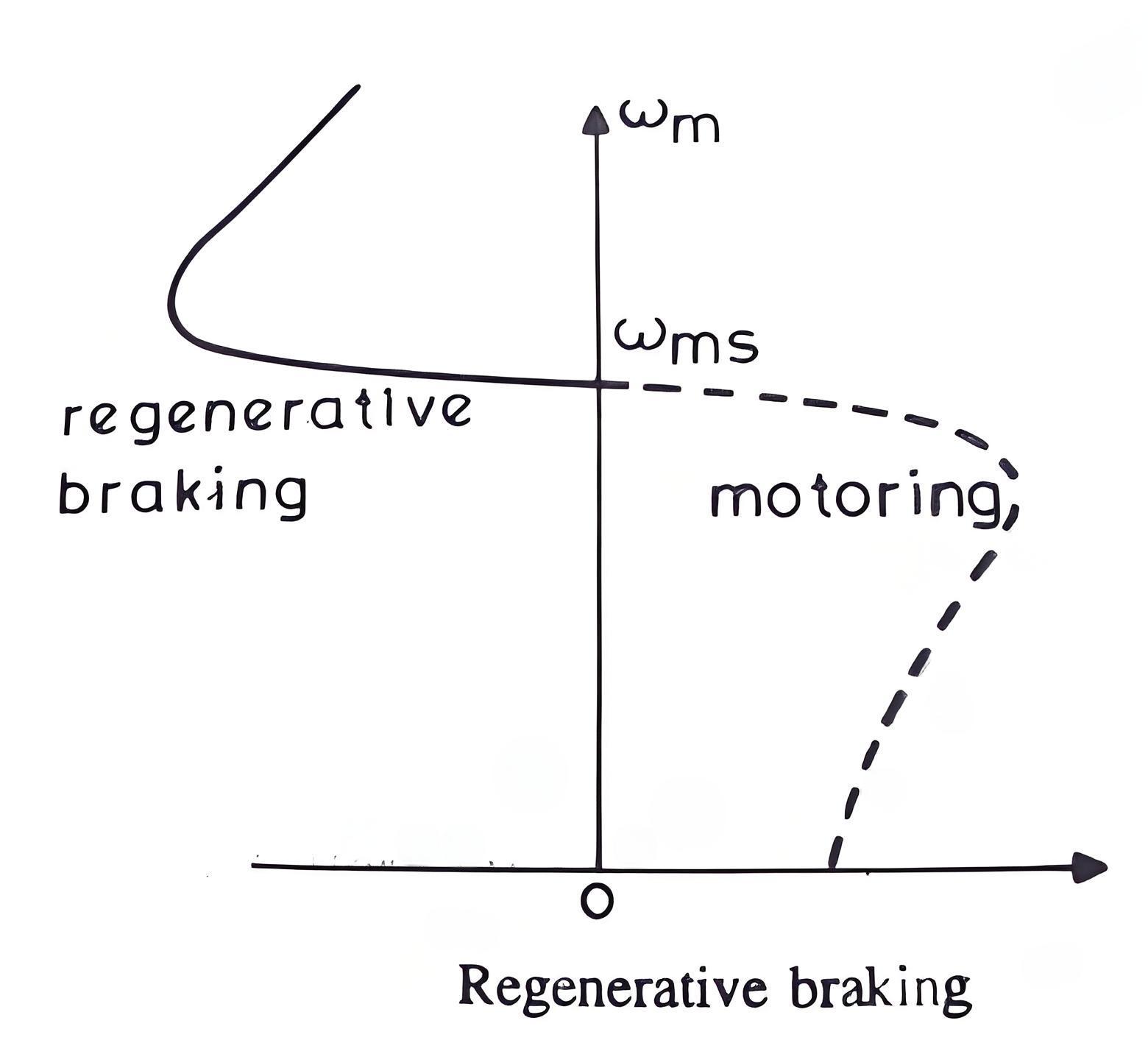
Here, φs the phase angle between stator phase voltage V and the stator phase current Is. Now, for motoring operation φs < 90o and for braking operation φs > 90o. When the speed of the motor is more than the synchronous speed, relative speed between the motor conductors and air gap rotating field reverses, as a result the phase angle because greater than 90o and the power flow reverse and thus regenerative braking takes place. The nature of the speed torque curves are shown in the figure beside. It the source frequency is fixed then the regenerative braking of induction motor can only take place if the speed of the motor is greater than synchronous speed, but with a variable frequency source regenerative braking of induction motor can occur for speeds lower than synchronous speed. The main advantage of this kind of braking can be said that the generated power is use fully employed and the main disadvantage of this type of braking is that for fixed frequency sources, braking cannot happen below synchronous speeds.

68f0c9ab6a743c8a6fc9c44cb2e0c502.jpeg

Plugging Braking

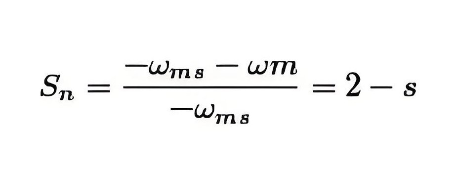
Plugging induction motor braking is done by reversing the phase sequence of the motor. Plugging braking of induction motor is done by interchanging connections of any two phases of stator with respect of supply terminals. And with that the operation of motoring shifts to plugging braking. During plugging the slip is (2 – s), if the original slip of the running motor is s, then it can be shown in the following way.

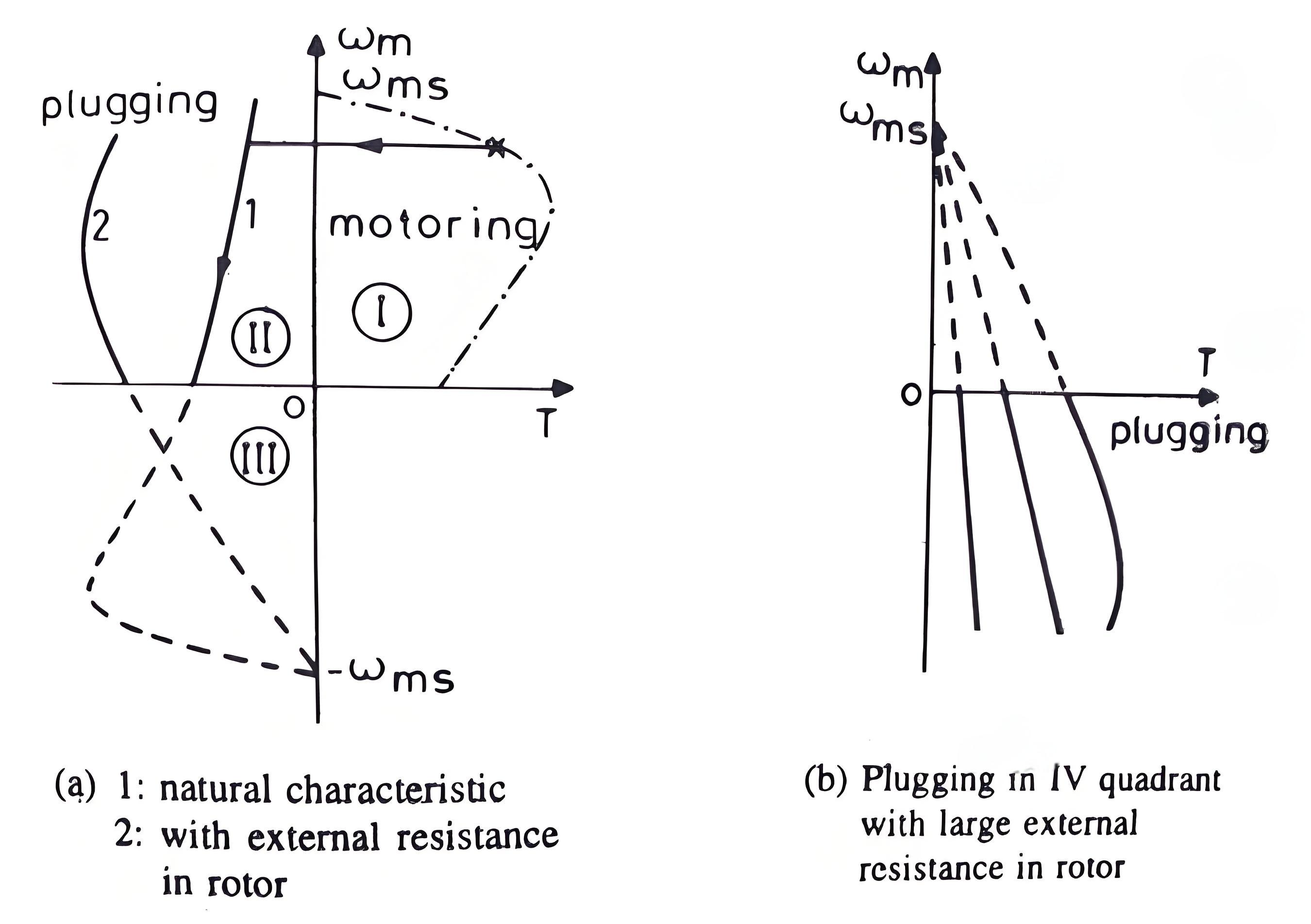
From the figure beside we can see that the torque is not zero at zero speed. That’s why when the motor is needed to be stopped, it should be disconnected from the supply at near zero speed. The motor is connected to rotate in the reverse direction and the torque is not zero at zero or any other speed, and as a result the motor first decelerates to zero and then smoothly accelerates in the opposite direction.

50e434b32ac3e68faaa9db5b98f1ae5b.jpeg

7669432f542e6cbe4497ed8261ad6e68.jpeg

AC Dynamic Braking

Involves disconnecting one phase, allowing the motor to run on a single phase, creating braking torque due to positive and negative sequence voltages.

Self Excited Braking

Uses capacitors to excite the motor when disconnected from the source, turning it into a generator and producing braking torque.

Give a tip and encourage the author!
Recommended
SG10 Series Transformer Overload Protection Solution | Prevent Overheating and Damage, View Now
Operating Conditions in National Standard GB 6450-1986Ambient temperature: Maximum ambient temperature: +40°C Daily average maximum temperature: +30°C Annual average maximum temperature: +20°C Minimum temperature: -30°C (outdoor); -5°C (indoor) Horizontal axis: Product load; Vertical axis: Average coil temperature rise in Kelvin (note: not in Celsius).For Class H insulation products, the long-term temperature resistance of insulation materials is stipulated by the state as 180°C. However, the in
Rockwell
09/12/2025
High harmonics? Your transformer may be overheating and aging fast.
This report is based on the analysis of one-day power quality monitoring data of your company's distribution system. The data shows that there is significant three-phase current harmonic distortion in the system (with a high total harmonic distortion of current, THDi). In accordance with international standards (IEC/IEEE), harmonic currents at this level have posed substantial risks to the safe, reliable, and economical operation of the power supply transformer, mainly manifested in additional h
Leon
09/12/2025
Comprehensive Analysis of Common Accessories of Dry-Type Transformers: From Enclosures to Copper Bars, Master Key Configurations in One Article
EnclosuresEnclosures can be categorized into indoor and outdoor types.For indoor applications, considering heat dissipation and maintenance needs, it is generally recommended not to install an enclosure if there is sufficient installation space. However, if required by the user, enclosures with multiple observation holes can be provided. Enclosures can also be painted in colors preferred by the user.The protection level of enclosures is typically IP20 or IP23: IP20 prevents the ingress of solid
Rockwell
09/08/2025
Transforming Power: The Future of Electric Transformers
Transformers are the "unsung heroes" of the modern world. These seemingly unremarkable devices, either hidden on utility poles or installed in substations, play an indispensable role in the power grid system—it is through them that electrical energy can be efficiently converted, transmitted, and utilized. Today, as humanity stands at the crossroads of an accelerating transformation in the energy landscape, recognizing the transformative potential of transformers and exploring how they will shape
Vziman
09/06/2025
Seed Inquiry
Download
Get the IEE Business Application
Use the IEE-Business app to find equipment, obtain solutions, connect with experts, and participate in industry collaboration anytime, anywhere—fully supporting the development of your power projects and business.