What is Motor Generator Set?

Encyclopedia
08/21/2024

What is Motor Generator Set?

Motor Generator Set Definition

A motor generator (M-G) set is defined as a device consisting of a motor and a generator mechanically coupled through a common shaft. It’s used to convert electrical power from one form to another, such as converting voltage, phase, or frequency.

b5d900e323cb06beeb984784731f054f.jpeg

8e6f21ebe50942b7b43d3d6146251bd6.jpeg

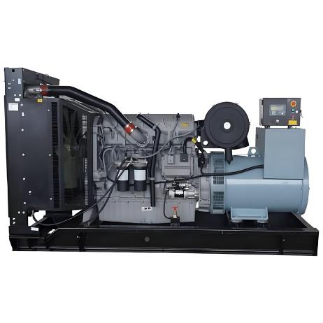
Motor generator sets also convert voltage, phase, and frequency of power. They help isolate electrical loads from the supply line. Here is a picture of an M-G set.

Here a motor and a generator are coupled together using a single shaft; they are wound around a single rotor. Necessary condition for coupling is that rated speed of both motor and generator should be same.

Applications

M-G sets convert voltage, phase, and frequency of power and isolate electrical loads from the supply line.

Working Principle

In a typical motor generator set, power is supplied to the motor, which rotates its shaft. This rotation, being mechanically coupled to the generator’s shaft, makes the generator convert this mechanical energy back into electrical energy.

Thus while the power at the input as well as output side is electrical in nature, the power flowing between the machines is in the form of mechanical torque. This provides isolation of the electrical system as well as some buffering of power between the two electrical systems.

Power Conversions

  • AC to DC – This is possible by using an AC motor (induction motor or synchronous motor) and a DC generator.

  • DC to AC – This can be accomplished by using a DC motor and an AC generator.

  • DC at some voltage level to DC at another voltage level.

  • Alternating power at one frequency to Alternating power at another frequency

  • Fixed AC voltage to variable or regulated AC voltage

  • Single phase AC voltage to 3 phase AC voltage

Nowadays, motor generator sets have been upgraded in many ways. They were used where precise speed regulation was needed, like in elevators and factories. Today, semiconductor devices such as thyristor, SCRs, GTOs, and MOSFET often replace M-G sets because they are compact, have lower losses, and are easier to control.

Modern Alternatives

Semiconductor devices such as thyristors and MOSFETs now often replace M-G sets due to their smaller size, reduced losses, and easier control.

Encyclopedia

The Electricity Encyclopedia is dedicated to accelerating the dissemination and application of electricity knowledge and adding impetus to the development and innovation of the electricity industry.

Cost Differences and Performance Comparison of 35kV New Energy Transformers Based on Dry-Type, Mineral Oil, and Vegetable Oil
For users, when purchasing a 35kV new energy transformer, choosing between dry-type, mineral oil-filled, or vegetable oil-filled types involves multiple considerations. These include user habits, maintenance-free performance, safety and fire resistance, volume and weight, among others. However, cost differences are undoubtedly one of the most crucial factors.To illustrate the issue intuitively, this paper selects a three-level energy efficiency dual-winding new energy transformer with a rated ca
Ron
07/26/2025
What is the connection group of a transformer?
Transformer Connection GroupThe connection group of a transformer refers to the phase difference between the primary and secondary voltages or currents. It is determined by the winding directions of the primary and secondary coils, the labeling of their start and end terminals, and the connection mode. Expressed in a clock-like format, there are 12 groups in total, numbered from 0 to 11.The DC method is commonly used to measure the transformer's connection group, mainly to verify whether the con
Vziman
07/26/2025
What is the sequence for powering down the transformer?
The sequence for shutting down a main transformer is as follows: when de-energizing, the load side should be shut down first, followed by the power supply side. For energizing operations, the reverse order applies: the power supply side is energized first, then the load side. This is because: Energizing from the power supply side to the load side makes it easier to identify the fault range and take prompt judgment and handling measures in case of a fault, preventing the fault from spreading or e
Rockwell
07/26/2025
What are the methods for switching operations of station transformers?
Let's take an auxiliary power system with two station transformers as an example. When one station transformer needs to be out of service, there are two operation methods: non-interruptive power supply and instantaneous power interruption. Generally, the method of instantaneous power interruption on the low-voltage side is preferred.The operation method for instantaneous power interruption on the low-voltage side is as follows:Open the 380V power incoming circuit breaker of the corresponding sec
Vziman
07/26/2025
Inquiry
Download
IEE-Business is dedicated to serving the personnel in the global power industry.
Join IEE-Business, not only can you discover power equipment and power knowledge, but also canhnd like - minded friends!