Why Is Compact Substation Grounding Resistance Usually ≤4Ω?

As a key power distribution equipment, the safe operation of a compact substation relies on reliable grounding measures. People often wonder: Why is the grounding resistance of a compact substation generally required to be no more than 4Ω? Behind this value, there are rigorous technical bases and application scenario restrictions. In fact, the requirement of ≤4Ω is not mandatory in all cases. It mainly applies to scenarios where the high - voltage system adopts "ungrounded", "resonant grounding", or "high - resistance grounding" methods. Because under these grounding methods, when a single - phase grounding fault occurs on the high - voltage side, the fault current is relatively small (usually no more than 10A). If the grounding resistance is controlled within 4Ω, the fault voltage can be limited to a relatively safe range (such as 40V), effectively avoiding the electric shock risk caused by the potential rise of the PE wire on the low - voltage side. The following text will deeply analyze the principles and logic behind this technical requirement.
Why is the grounding resistance of a compact substation usually required to be no greater than 4 Ω? Actually, the requirement that the grounding resistance should be ≤ 4 Ω has applicable conditions and does not apply to all situations. This standard mainly applies to scenarios where the high-voltage system adopts ungrounded, resonant grounding, or high-resistance grounding methods, rather than to situations where the high-voltage system uses effective grounding.
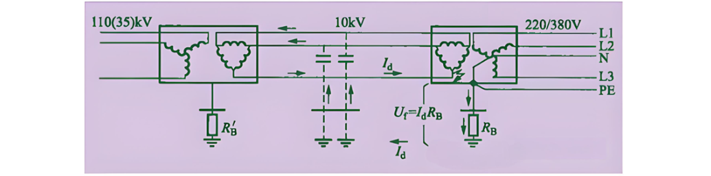
In the above three grounding methods (ungrounded, resonant grounding, and high-resistance grounding), the single-phase ground fault current of the high-voltage system is relatively small, usually not exceeding 10 A. When such a fault current flows through the grounding resistance Rb of the compact substation, a voltage drop will be generated across it. If Rb is 4 Ω, the voltage drop is:U=I×R=10A×4Ω=40V
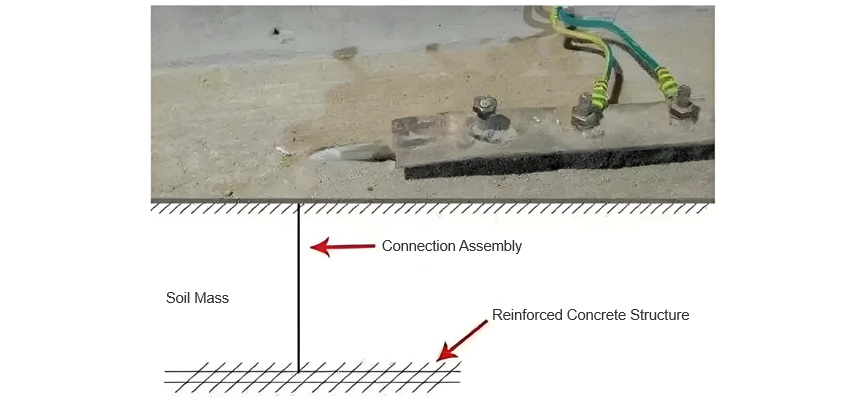
Since the protective grounding of the high-voltage system and the system grounding of the low-voltage distribution system often share the same grounding electrode, the potential of the PE wire on the low-voltage side to the ground will also rise to 40 V. This voltage is lower than the safety limit for human electric shock (the contact voltage limit is generally considered to be 50 V), thus greatly reducing the risk of personal electric shock accidents on the low-voltage side when a ground fault occurs on the high-voltage side.
According to the relevant standards (such as "Code for Grounding Design of AC Electrical Installations" GB/T 50065-2014), Article 6.1.1 stipulates:
For high-voltage power distribution equipment that operates in non-grounded, resonant-grounded and high-resistance-grounded systems and supplies power to low-voltage electrical devices of 1kV and below, the grounding resistance of the protective grounding should meet the following requirements and should not exceed 4Ω: R ≤ 50 / I
R: Consider the maximum grounding resistance after considering seasonal variations (Ω);
I: The single-phase grounding fault current for calculation. In a resonant grounding system, the residual current at the fault point is used as the basis for the translation.
In summary, limiting the grounding resistance of a compact substation to within 4Ω is intended to effectively control the contact voltage within a safe range and ensure personal safety when a ground fault occurs on the high-voltage side. This requirement is the result of safety design based on specific grounding systems and fault current levels.


