SST Transformer Core Loss Calculation and Winding Optimization Guide

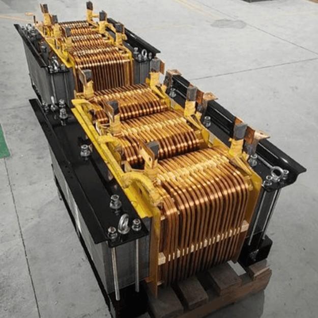
SST High-Frequency Isolated Transformer Core Design and Calculation
Material Characteristics Impact:Core material exhibits varying loss behavior under different temperatures, frequencies, and flux densities. These characteristics form the foundation of overall core loss and require precise understanding of nonlinear properties.
Stray Magnetic Field Interference:High-frequency stray magnetic fields around windings can induce additional core losses. If not properly managed, these parasitic losses may approach the intrinsic material losses.
Dynamic Operating Conditions:In LLC and CLLC resonant circuits, the voltage waveform and operating frequency applied to the core vary dynamically, making instantaneous loss calculation significantly more complex.
Simulation and Design Requirements:Due to the coupled multi-variable and highly nonlinear nature of the system, accurate total loss estimation is difficult to achieve manually. Precise modeling and simulation using specialized software tools are essential.
Cooling and Loss Requirements: High-power high-frequency transformers have a smaller surface area-to-capacity ratio, necessitating forced cooling. Core losses in nanocrystalline materials must be precisely calculated and combined with thermal analysis of the cooling system to evaluate temperature rise.
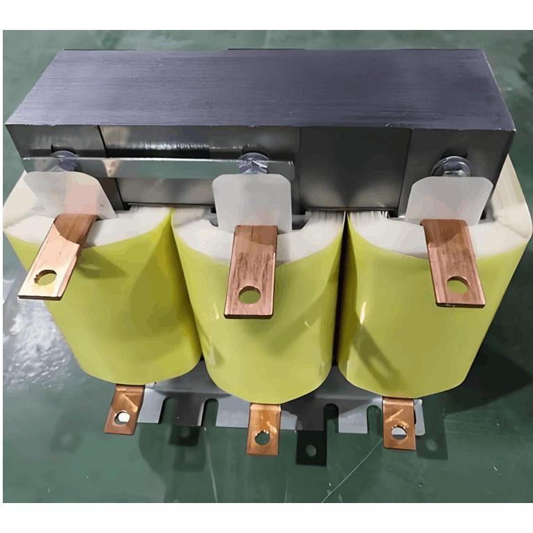
(1) Winding Design and Calculation
AC Losses: At high frequencies, increased current frequency leads to higher winding resistance. The impedance per unit conductor must be calculated using specific formulas.

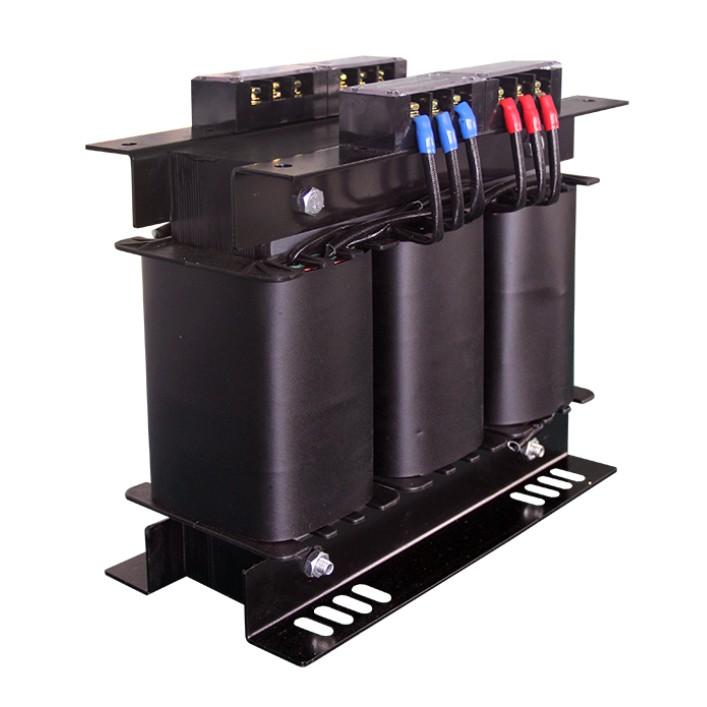
(2) Eddy Current Losses
Skin Effect: When AC current flows through a round conductor, concentric alternating magnetic fields are generated, inducing eddy current losses.
Proximity Effect: In multi-layer windings, the current in one layer affects the current distribution in adjacent layers. The AC-to-DC resistance ratio must be calculated using Dowell's formula.

where △ is the ratio of winding thickness to skin depth, and p is the number of winding layers);
Risk Warning: Windings designed by inexperienced engineers may suffer high-frequency AC losses several times greater than the copper losses of a 50Hz transformer of the same capacity.
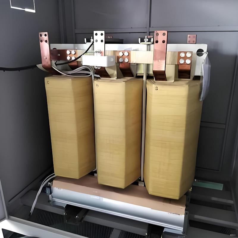
Issues with Amorphous and Nanocrystalline Materials
(1) Core Consistency Issues
Even within the same batch and identical specifications, nanocrystalline cores can exhibit significant differences in heating (losses) under high-frequency current excitation. Incoming inspection is required through parameters such as weight (indicating density/filling factor), Q-value (assessing losses), inductance (evaluating permeability), and temperature rise testing under power to evaluate losses.
(2) Loss and Material Limitations
Cut-Edge Loss: Magnetic field concentration at cut edges increases eddy current losses, making these areas the hottest spots and compromising thermal stability.
Uneven Loss Distribution: Besides cut edges, multiple hotspots still exist along the magnetic path.
Material Limitations: Amorphous and nanocrystalline materials struggle to meet resonant circuit requirements for low permeability. They generate significant noise below 16 kHz and are highly sensitive to mechanical stress.