Efficiency of Transformer

Electrical4u
04/30/2024

16d6c2289f8bafeaffe95ee1086b6bc.png

Introduction of Efficiency of Transformer

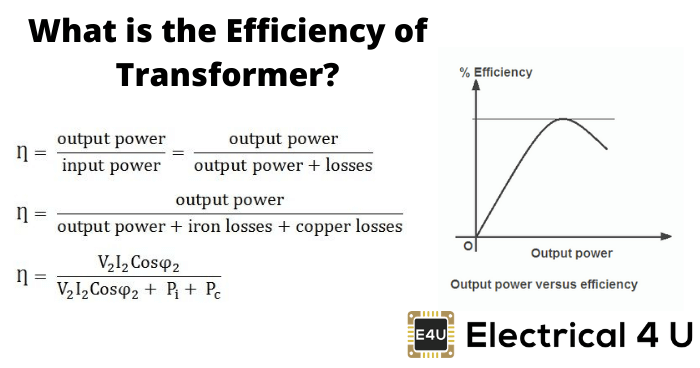
Transformers form the most important link between supply systems and load. Transformer’s efficiency directly affects its performance and aging. The transformer’s efficiency, in general, is in the range of 95 – 99 %. For large power transformers with very low losses, the efficiency can be as high as 99.7%. The input and output measurements of a transformer are not done under loaded conditions as the wattmeter readings inevitably suffer errors of 1 – 2%. So for the purpose of efficiency calculations, OC and SC tests are used to calculate rated core and winding losses in the transformer. The core losses depend on the transformer rated voltage, and the copper losses depend on the currents through the transformer primary and secondary windings. Hence transformer efficiency is of prime importance to operate it under constant voltage and frequency conditions. The rise in the temperature of the transformer due to heat generated affects the life of transformer oil properties and decides the type of cooling method adopted. The temperature rise limits the rating of the equipment. The efficiency of transformer is simply given as:

  • The output power is the product of the fraction of the rated loading (volt-ampere), and power factor of the load

  • The losses are the sum of copper losses in the windings + the iron loss + dielectric loss + stray load loss.

  • The iron losses include the hysteresis and eddy current losses in the transformer. These losses depend on the flux density inside the core. Mathematically,
    Hysteresis Loss :

    Eddy Current Loss :

    Where kh and ke are constants, Bmax is the peak magnetic field density, f is the source frequency, and t is the thickness of the core. The power ‘n’ in the hysteresis loss is known as Steinmetz constant whose value can be nearly 2.

  • The dielectric losses take place inside the transformer oil. For low voltage transformers, it can be neglected.

  • The leakage flux links to the metal frame, tank,etc. to produce eddy currents and are present all around the transformer hence called stray loss, and it depends on the load current and so named as ‘stray load loss.’ It can be represented by resistance in series to the leakage reactance.

Efficiency Calculation of the Transformer

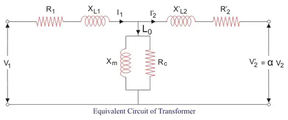
The equivalent circuit of transformer referred to primary side is shown below. Here Rc accounts for core losses. Using Short circuit(SC) test, we can find the equivalent resistance accounting for copper losses as

{CA38F734-D59B-42c6-8B13-82D0C0BF1DF5}.png

Let us define x% be the percentage of full or rated load ‘S’ (VA) and let Pcufl(watts) be the full load copper loss and cosθ be the power factor of the load. Also, we defined Pi (watts) as core loss. As copper and iron losses are major losses in the transformer hence only these two types of losses are taken into account while calculating efficiency. Then the efficiency of transformer can be written as :

Where, x2Pcufl = copper loss(Pcu) at any loading x% of full load.
The maximum efficiency (ηmax) occurs when the variable losses equal to the constant losses. Since the copper loss is load dependent, hence it is a variable loss quantity. And the core loss is taken to be the constant quantity. So the condition for maximum efficiency is :

{2FE6E547-10CA-4cf9-9224-E75E5FBB7AD1}.png

Now we can write maximum efficiency as :

This shows that we can obtain maximum efficiency at full load by proper selection of constant and variable losses. However, it is difficult to obtain maximum efficiency as copper losses are much higher than the fixed core losses.
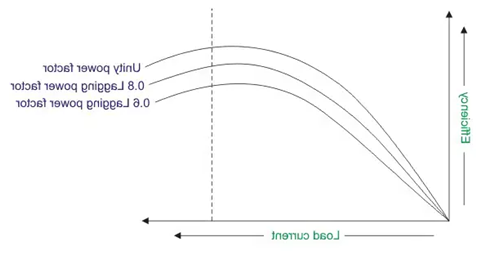
The variation of efficiency with loading can be represented by figure below :

{204A16D3-2565-42fb-ABA4-77810A760730}.png

We can see from the figure that the maximum efficiency occurs at unity power factor. And the maximum efficiency occurs at same loading irrespective of power factor of the load.


All Day Efficiency of Transformer

It is an energy-based efficiency calculated for distribution transformers. Unlike power transformer which is switched in or out depending on the load handled by it, a distribution transformer loading continuously fluctuates for 24 hours a day. As core losses are independent of load, the all-day efficiency depends on the copper losses.We define it as the ratio of output energy delivered to input energy for a 24 hour cycle. High energy efficiencies are achieved by restricting core flux densities to lower values (as the core losses are dependent on flux density) by using relatively larger cross-section or larger iron/copper weight ratio.

Statement: Respect the original, good articles worth sharing, if there is infringement please contact delete.

Electrical4u

Electrical4U is dedicated to the teaching and sharing of all things related to electrical and electronics engineering.

Can a power transformer designed for 50Hz operate normally at a frequency of 60Hz?
Can a 50Hz-Designed Power Transformer Operate on 60Hz Grid?If a power transformer is designed and built for 50Hz, can it run on a 60Hz grid? If so, how do its key performance parameters change?Key Parameter ChangesShort-Circuit Impedance:For a given transformer (same voltage and capacity), short-circuit impedance is proportional to frequency. Thus, a 50Hz-designed unit operating at 60Hz sees a 20% increase—higher frequency intensifies alternating leakage field opposition to current.No-Load
Vziman
07/29/2025
What are the basic processes and key points in transformer simulation design?
1 IntroductionWhether using any finite element analysis software (such as COMSOL, Infolytica, or Ansys) for transformer simulation analysis—whether focusing on electric field, magnetic field, flow field, mechanical field, or acoustic field—the basic process is roughly the same. A true understanding of the key points in each process is the foundation for the success of the simulation analysis and the reliability of the final results.2 Basic Simulation ProcessA scientific and complete
Ron
07/29/2025
Sharing of Transformer Concepts and Terminology
Sharing of Transformer Concepts and TerminologyThe zero-mode impedance of a load is infinite, and its line-mode impedance is also extremely large, approximately 100 times that of the line-mode impedance of the line.The capacitance to ground of a cable is 25-50 times that of an overhead line.The free oscillation frequency of transient capacitive current: 300-1500Hz for overhead lines and 1500-3000Hz for cables.Performance requirements for an external grounding transformer: Under normal power supp
Edwiin
07/28/2025
Example of Process Improvement for Enhancing Consistency of Small - Batch High - Temperature Special Transformers
Given the lack of manufacturers for such transformers on the market, we design them in - house. We provide technical specs to partners, specifying materials like high - temp enameled wires.Electrical signals from downhole logging tools, transmitted via these transformers, impact formation - to - surface signal reliability. Thus, improving transformer consistency boosts signal uniformity, enhancing logging tool accuracy and our market competitiveness.Our common signal transformers are EI - type,
Vziman
07/28/2025
Inquiry
Download
IEE-Business is dedicated to serving the personnel in the global power industry.
Join IEE-Business, not only can you discover power equipment and power knowledge, but also canhnd like - minded friends!