EMF Equation of Transformer

EMF Equation of Transformer Definition
The EMF equation of a transformer is derived using Faraday’s law, indicating the induced EMF based on flux changes and winding turns.

Magnetizing Current
An alternating current in the primary winding generates a magnetizing current that produces alternating flux in the transformer’s core.
Sinusoidal Flux and EMF
The sinusoidal primary current creates a sinusoidal flux, and its rate of change (cosine function) determines the induced EMF.
Voltage and Turns Ratio
The ratio of primary to secondary voltage (voltage ratio) is directly proportional to the ratio of the number of turns in the primary and secondary windings (turns ratio).

Transformation Ratio
The transformation ratio (K) indicates whether a transformer is step-up (K > 1) or step-down (K < 1), based on the primary and secondary windings.


-
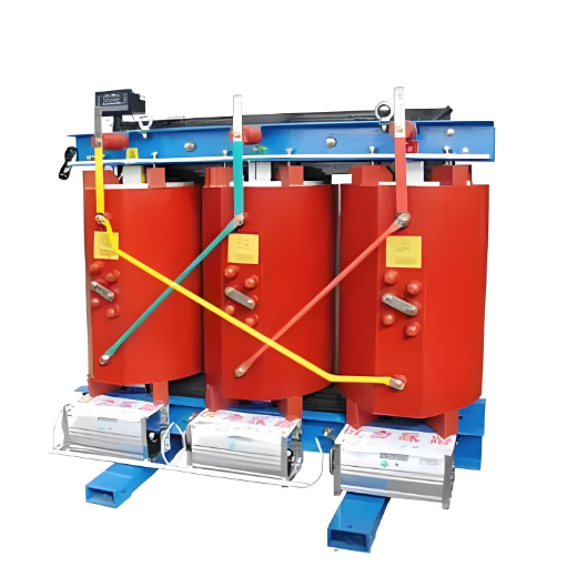
10.5kV Silicon Steel Dry Type Distribution Transformer 630kVA/800kVA/1000kVA/1250kVA /1600kVA/2000kVA
-
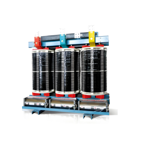
Non-encapsulated Class H dry-type power transformer 200kVA 250kVA 315kVA 400kVA
-
High-voltage Permanent Magnet Mechanism Vacuum Switch for Mining Flameproof Mobile Substations

-
YDG Series test transformer


