What is Transformer Inrush Current?

What is Transformer Inrush Current?
Transformer Inrush Current Definition
Transformer inrush current is defined as the high transient current drawn by a transformer when it is energized.
Initial Flux and Voltage
At startup, there is no initial flux, and the flux wave starts from zero, following the voltage waveform.

Peak Flux and Core Saturation
The flux can peak at double the steady-state maximum value, leading to core saturation and high inrush current.
Transient Nature of Inrush Current
Inrush current is transient, lasting only a few milliseconds, but can be up to 10 times the normal rated current.

Impact on Circuit Operation
High inrush current can cause fuse or breaker interruptions, component failures, and introduce noise and distortion into the electrical system.


-
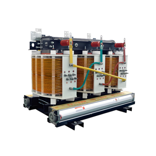
33-38kV Dry-type Distribution Transformer 800kVA/1000kVA/1250kVA/1500kVA

-
High-voltage Permanent Magnet Mechanism Vacuum Switch for Mining Flameproof Mobile Substations

-
Non-encapsulated Class H dry-type power transformer 200kVA 250kVA 315kVA 400kVA
-
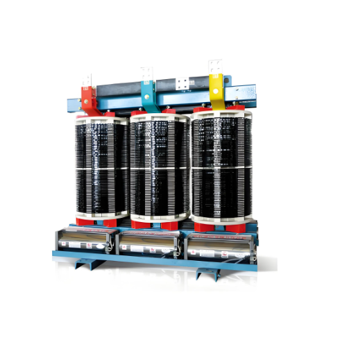
Non-encapsulated H-class Dry-type Power Transformers 800kVA 1000kVA 1250kVA 1600kVA 2000kVA 2500kVA