Open & Short Circuit Transformer Tests

Open and short circuit tests are performed on a transformer to determine the:
Equivalent circuit of transformer
Voltage regulation of transformer
Efficiency of transformer
Open Circuit Test Definition
The open circuit test of a transformer checks the core losses and parameters of the shunt branch by connecting instruments to the LV side and keeping the HV side open.

Open-circuit Test (No-load Test) Steps:
Ensure that the transformer is disconnected from the power supply to ensure safety.
Open the low-voltage side winding of the transformer.
Apply the rated voltage to the high-voltage side winding.
Use appropriate instruments to measure the input voltage, current and power on the high-voltage side.
Record the measured data, including voltage, current and power.
Through the open-circuit test, the following important parameters can be obtained:
No-load current: It reflects the excitation characteristics and core losses of the transformer core.
No-load loss: Mainly core losses, including hysteresis loss and eddy current loss.
Short Circuit Test Definition
The short circuit test of a transformer determines copper losses and equivalent circuit parameters by applying a low voltage to the HV side and short-circuiting the LV side.

Short-circuit Test Steps:
Also ensure that the transformer is in a power-off state and take safety measures.
Short-circuit the high-voltage side winding of the transformer.
Apply a lower voltage to the low-voltage side winding to make the winding current reach the rated current.
Measure the input voltage, current and power at this time.
Record the relevant data.
The short-circuit test is mainly used to determine the following parameters:
Short-circuit impedance: It reflects the resistance and leakage reactance of the transformer winding.
Short-circuit loss: Mainly the resistance loss of the winding.
These two tests are of great significance for evaluating the performance, efficiency, quality of the transformer and determining whether there is a fault.
Sum up
The open circuit and short circuit test of transformer is an important means to evaluate the performance and health of transformer. Through these tests, key parameters such as no-load current, no-load loss, equivalent impedance and leakage inductance reactance of the transformer can be determined to optimize the design and operation of the transformer. In practice, it is necessary to strictly follow the test procedure to ensure the accuracy and reliability of the test results.


-
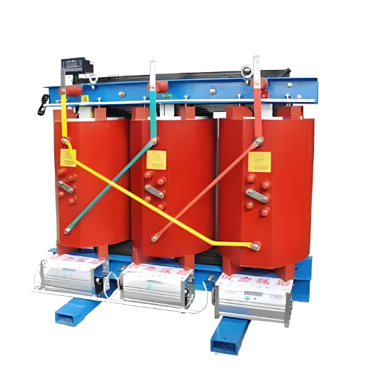
6.3kV Cast Resin 3 Phase Dry Type Distribution Transformer

-
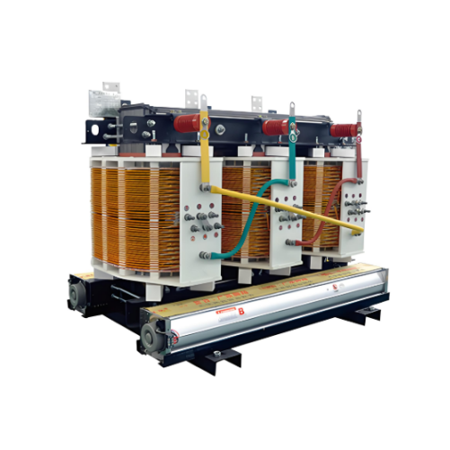
Non-encapsulated H-class Dry-type Power Transformers 800kVA 1000kVA 1250kVA 1600kVA 2000kVA 2500kVA
-
Dry-Type Transformers for Ships and Oil Drilling Platforms

-
10.5kV Silicon Steel Dry Type Distribution Transformer 630kVA/800kVA/1000kVA/1250kVA /1600kVA/2000kVA