Ward Leonard Method Of Speed Control Or Armature Voltage Control

The Ward Leonard method of speed control operates by adjusting the voltage applied to the armature of a motor. This innovative approach was first introduced in 1891, marking a significant advancement in the field of electrical motor control. The figure below illustrates the connection diagram for implementing the Ward Leonard method to control the speed of a DC shunt motor, providing a clear visual representation of the system's configuration and operation.
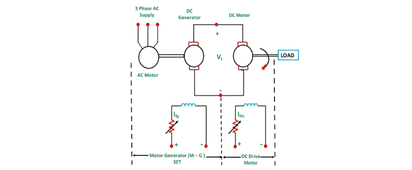
In the system described above, M represents the main DC motor whose rotational speed is the target of control, while G is a separately excited DC generator. The generator G is powered by a three - phase driving motor, which can be either an induction motor or a synchronous motor.The pairing of the AC driving motor and the DC generator is commonly referred to as the Motor - Generator (M - G) set.
The voltage output of the generator can be adjusted by modifying the generator's field current. When this adjusted voltage is directly supplied to the armature of the main DC motor, it causes a corresponding change in the speed of motor M. To ensure consistent performance during speed control, the motor's field current Ifm is maintained at a constant level, which in turn keeps the motor's field flux ϕm stable. Additionally, while controlling the motor's speed, the motor armature current Ia is regulated to match its rated value.By varying the generated field current Ifg, the armature voltage Vt can be adjusted from zero to its rated value.
This adjustment in voltage results in the motor's speed changing from zero to its base speed. Since the speed control process is executed with the rated current Ia and a constant motor field flux ϕm, a constant torque is achieved, as torque is directly proportional to the product of the armature current and the field flux up to the rated speed. Given that the product of torque and speed defines power, and torque remains constant in this scenario, power becomes directly proportional to speed.Consequently, as the power output increases, the speed of the motor increases accordingly.
The torque and power characteristics of this speed - control system are illustrated in the figure below, providing a visual representation of how these parameters interact and change during operation.
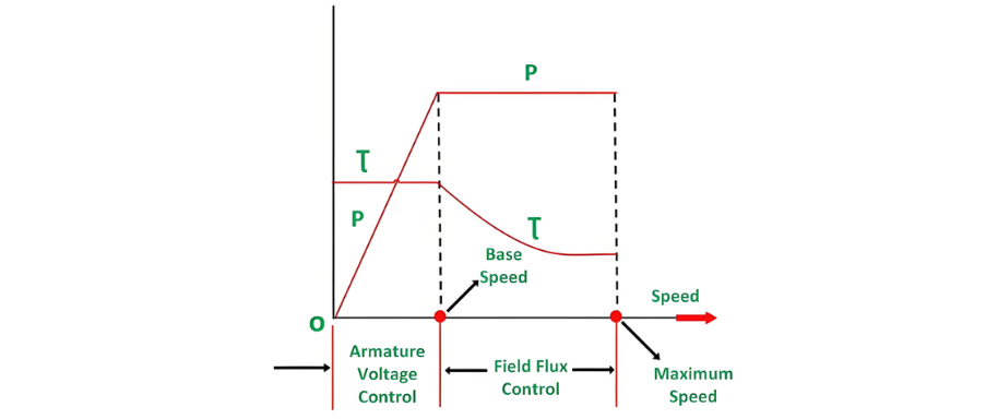
In summary, the armature voltage control method enables the achievement of a constant torque and variable power drive for speeds below the base speed. On the other hand, the field flux control method comes into play when the speed exceeds the base speed. In this operational mode, the armature current is consistently maintained at its rated value, and the generator voltage Vt remains constant.
When the motor field current is decreased, the motor field flux also diminishes, effectively weakening the field to achieve higher speeds. Given that Vt Ia and E Ia remain constant, the electromagnetic torque is directly proportional to the product of the field flux ϕm and the armature current Ia. Consequently, a reduction in the motor's field flux leads to a decrease in torque.
As a result, torque decreases as the speed increases. Thus, in the field control mode, for speeds above the base speed, a constant power and variable torque operation is obtained. When a wide - range speed control is necessary, a combination of armature voltage control and field flux control is employed. This combined approach allows the ratio of the maximum to minimum available speeds to range from 20 to 40. In closed - loop control systems, this speed range can be extended up to 200.
The driving motor can be either an induction motor or a synchronous motor. An induction motor typically operates at a lagging power factor. By contrast, a synchronous motor can be operated at a leading power factor through over - excitation of its field. An over - excited synchronous motor generates leading reactive power, which effectively compensates for the lagging reactive power consumed by other inductive loads, thereby improving the overall power factor.
When dealing with heavy and intermittent loads, a slip ring induction motor is often utilized as the prime mover, and a flywheel is mounted on its shaft. This configuration, known as the Ward Leonard - Ilgener scheme, helps to prevent significant fluctuations in the supply current. However, when a synchronous motor serves as the driving motor, mounting a flywheel on its shaft cannot reduce fluctuations, since a synchronous motor always runs at a constant speed.
Advantages of Ward Leonard Drives
The Ward Leonard drive offers several key advantages:
It allows for smooth speed control of a DC motor over a broad range in both directions.
It has an inherent braking capability.By using an over - excited synchronous motor as the drive, the lagging reactive volt - amperes are compensated, enhancing the overall power factor.
In applications with intermittent loads, such as rolling mills, an induction motor with a flywheel can be employed to smooth out the intermittent loading, reducing its impact on the system.
Drawbacks of Classical Ward Leonard System
The classical Ward Leonard system, which relies on rotating Motor - Generator sets, has the following limitations:
The initial investment for the system is substantial due to the requirement of installing a motor - generator set with the same rating as the main DC motor.
It has a large physical size and significant weight.
It demands a large floor area for installation.The foundation required for the system is costly.
Frequent maintenance is needed.
It incurs higher losses during operation.
Its overall efficiency is relatively low.
The drive generates a significant amount of noise.
Applications of Ward Leonard Drives
Ward Leonard drives are ideal for scenarios where smooth, bidirectional, and wide - range speed control of DC motors is essential. Some common applications include:
Rolling mills
Elevators
Cranes
Paper mills
Diesel - electric locomotives
Mine hoists
Solid State Control or Static Ward Leonard System
In modern applications, the Static Ward Leonard system is widely preferred. In this system, the traditional rotating motor - generator (M - G) set is replaced by a solid - state converter for controlling the speed of the DC motor. Controlled rectifiers and choppers are commonly used as converters.
When the power source is an AC supply, controlled rectifiers are utilized to transform the fixed AC supply voltage into a variable DC supply voltage. In the case of a DC supply, choppers are employed to obtain a variable DC voltage from the fixed DC source.
In an alternative form of the Ward Leonard drive, non - electrical prime movers can also be used to drive the DC generator. For instance, in DC electric locomotives, the DC generator is powered by a diesel engine or a gas turbine, and this setup is also applicable in ship propulsion drives. In such systems, regenerative braking is not feasible because energy cannot flow in the reverse direction through the prime mover.


