Methods of Earthing

Earthing Methods and Earthing Mats
In electrical systems, there are multiple earthing methods available, including wire or strip earthing, rod earthing, pipe earthing, plate earthing, and earthing through water mains. Among these, pipe earthing and plate earthing are the most commonly employed, and they will be explored in detail below.
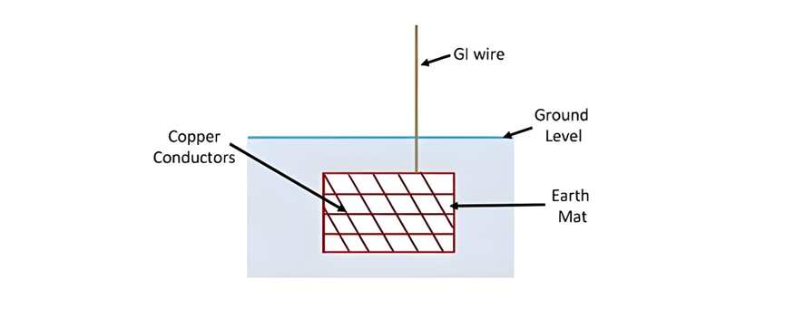
Earthing Mat
An earthing mat is constructed by connecting multiple rods with copper conductors. This configuration effectively reduces the overall grounding resistance and plays a crucial role in limiting ground potential. It is particularly suitable for areas where large fault currents are expected. When designing an earthing mat, several critical factors must be carefully considered:
Safety Considerations
During a fault condition, the voltage difference between the ground and the ground surface must be kept at a level that poses no danger to individuals who might come into contact with the non - current - carrying conductive surfaces of the electrical system. This ensures the safety of personnel working around or near the electrical installation.
Protective Relay Operation
The earthing mat should be capable of handling uninterrupted fault currents large enough to trigger the protective relay. A low ground resistance is essential to allow the fault current to flow freely through the mat, enabling the protective relay to operate promptly and isolate the faulty section of the electrical system.
Preventing Fatal Currents
The resistance of the earthing mat must be carefully designed to prevent the flow of fatal currents through a person's body in the event of accidental contact with live parts. This is a fundamental safety requirement to protect human life.
Step Voltage Limitation
The design of the grounding mat should ensure that the step voltage - the potential difference between two points on the ground surface a certain distance apart - remains below the permissible value. This permissible value depends on various factors, such as the resistivity of the soil and the fault conditions necessary to isolate the faulty equipment from the live electrical system. By keeping the step voltage within safe limits, the risk of electrical shock to individuals walking near the earthed installation is minimized.
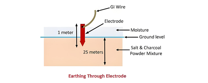
Earthing Electrodes
An earthing electrode refers to any wire, rod, pipe, plate, or a cluster of conductors that is inserted into the ground, either horizontally or vertically. In electrical distribution systems, a common form of the earth electrode is a rod, typically around 1 meter in length, which is driven vertically into the ground. This simple yet effective design helps to establish a reliable connection between the electrical system and the earth, facilitating the safe dissipation of fault currents.
In contrast, within generating substations, instead of relying on individual rods, a grounding mat is often employed. A grounding mat consists of multiple conductors interconnected to form a network. This approach offers several advantages over using single electrodes. The larger surface area and interconnected nature of the grounding mat provide lower overall resistance, enabling it to handle higher fault currents more effectively. Additionally, it helps to distribute the electrical potential more evenly across the substation area, reducing the risk of dangerous step and touch voltages that could pose a threat to personnel and equipment.
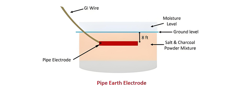
Pipe Earthing
Among various earthing methods applicable under the same soil and moisture conditions, pipe earthing stands out as one of the most prevalent and highly effective systems. In this approach, a galvanized steel pipe with perforations, conforming to approved specifications regarding length and diameter, is vertically installed in soil that remains permanently moist, as depicted in the accompanying illustration.
The selection of the pipe's size is a critical consideration, as it is determined by two primary factors: the magnitude of the current the earthing system needs to conduct and the characteristics of the soil. A larger - diameter pipe or a longer pipe may be required to handle higher fault currents, ensuring that the electrical charge can be safely and efficiently dissipated into the ground. Additionally, different soil types have varying electrical resistivities; for instance, soil with higher resistivity may necessitate a larger - sized pipe to achieve the desired low - resistance connection with the earth. This meticulous sizing process guarantees the reliability and safety of the pipe earthing system, making it a preferred choice for a wide range of electrical installations.
For pipe earthing, standard practice dictates specific dimensions for the earthing pipe, which vary according to soil conditions. Typically, in ordinary soil, a pipe with a diameter of 40 mm and a length of 2.5 meters is used. However, in dry and rocky soil, a longer pipe is necessary to ensure an effective connection to the earth. The depth at which the pipe is buried is directly related to the moisture content of the ground, as a more moist environment facilitates better electrical conductivity.
In a typical installation, the pipe is positioned at a depth of 3.75 meters. To enhance its performance, the bottom of the pipe is surrounded by small pieces of coke or charcoal, placed approximately 15 cm away. Alternating layers of coke and salt are employed, serving distinct purposes. The coke increases the effective contact area with the earth, while the salt reduces the earth resistance, collectively optimizing the earthing system's efficiency.
An additional pipe, measuring 19 mm in diameter and having a minimum length of 1.25 meters, is connected to the top of the galvanized iron (GI) pipe via a reducing socket. This secondary pipe plays a crucial role in maintaining the system's functionality, especially during adverse weather conditions.
During the summer months, the moisture content in the soil naturally decreases, leading to an increase in earth resistance. To counteract this, a cement concrete structure is constructed to ensure a consistent water supply. To maintain an effective earth connection, 3 to 4 buckets of water are poured through a funnel attached to the 19 mm - diameter pipe, which is connected to the main GI pipe. The earth wire, which can be either a GI wire or a GI wire strip with a sufficient cross - section to safely carry fault currents, is run through a 12 - mm - diameter GI pipe buried approximately 60 cm below the ground surface.
Plate Earthing
Plate earthing involves burying an earthing plate into the ground. The plate can be made of either copper, with dimensions of 60 cm × 60 cm × 3 mm, or galvanized iron, with dimensions of 60 cm × 60 cm × 6 mm. The plate is positioned vertically, with its top at a depth of not less than 3 meters from the ground surface. This depth is critical for ensuring reliable electrical grounding, as it allows the plate to make sufficient contact with the soil, facilitating the safe dissipation of electrical currents in the event of a fault.
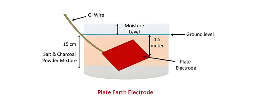
Plate Earthing
When implementing plate earthing, the earthing plate is inserted into auxiliary layers of coke and salt, with a minimum thickness of 15 cm for these layers. This combination helps to reduce soil resistivity around the plate, enhancing the effectiveness of the earthing system. An earth wire, made of either galvanized iron (GI) or copper, is then firmly attached to the earthing plate using nuts and bolts. Despite copper's superior electrical conductivity, copper plates and wires are not commonly used for grounding due to their significantly higher cost compared to GI alternatives. This cost - effectiveness makes GI materials the preferred choice for most practical earthing applications.
Earthing Through Water Mains
Earthing through water mains is another method of establishing an electrical connection to the earth. In this approach, a GI or copper wire is connected to the water mains. The connection is secured using steel binding wire, which is fastened to a copper lead. This method takes advantage of the extensive metal network of water mains, which typically have good contact with the ground, to provide a low - resistance path for electrical current in the event of a fault. However, this earthing method must comply with relevant safety regulations and plumbing codes to ensure both electrical safety and the integrity of the water supply system.
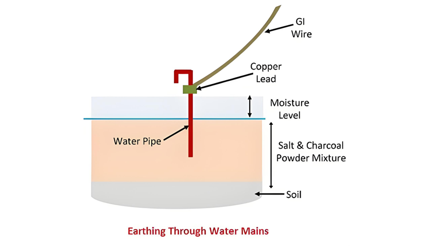
Water pipes are typically constructed from metal and are buried beneath the ground's surface, effectively establishing a direct connection to the earth. In the event of a fault, the current that flows through the galvanized iron (GI) or copper wire used for earthing is channeled directly into the ground via the water pipe. This provides a convenient and often effective pathway for dissipating fault currents, leveraging the water pipe's extensive underground network and its inherent conductivity as a metal structure.


