Application of Relays in Signal Systems

What is a Relay?
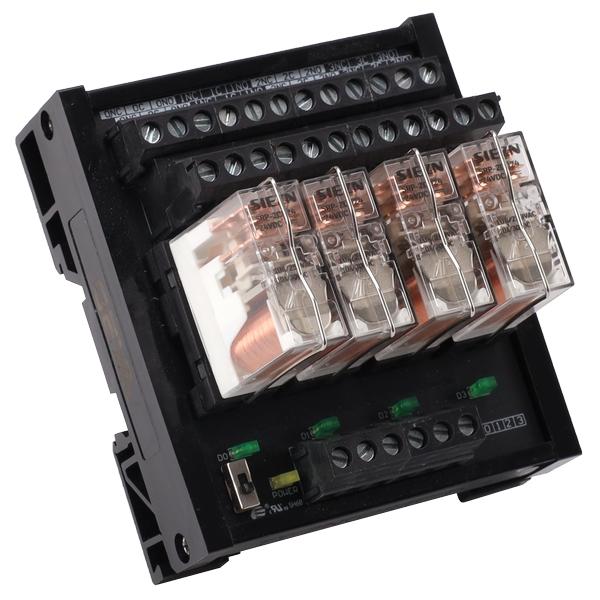
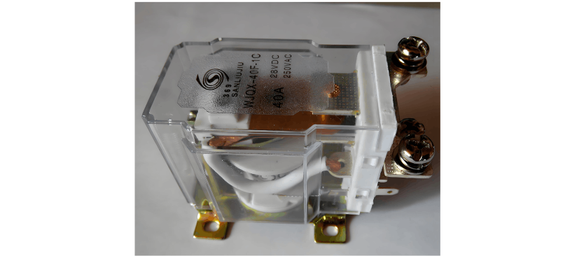
A relay is an electrical switch that uses electromagnetic force to control the opening and closing of one or more electrical circuits. It typically consists of core components such as an electromagnet, contacts, and springs. When the coil of the electromagnet is energized, it generates a magnetic field that attracts or releases an armature, thereby driving the contacts to actuate and achieve circuit connection or disconnection.
Classification of Relays
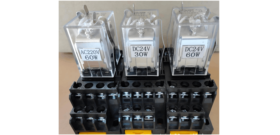
Relays are primarily divided into two major categories: DC Relays and AC Relays.
-
DC Relays:
- Power Supply: Powered by a DC source.
- Classification: Based on the polarity of the current, they can be categorized as Non-polarized Relays, Polarized Relays, and Biased Relays.
- Principle: All are electromagnetic relays that operate by using the magnetic field generated from the energized coil to attract an armature, which in turn drives the contact system to actuate.
-
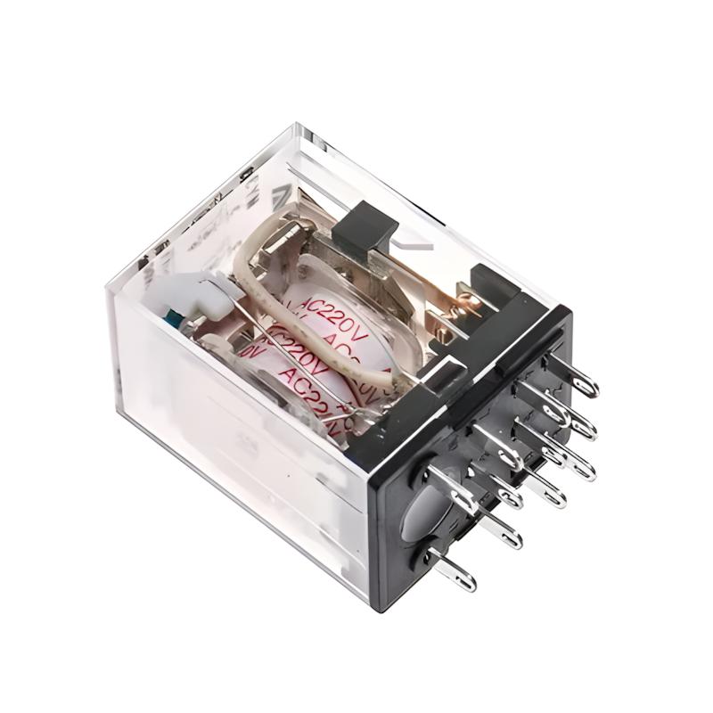
AC Relays:
- Power Supply: Powered by an AC source.
- Classification: Based on the operating principle, they include both Electromagnetic Relays and Induction Relays.
- Electromagnetic Relay: Operates similarly to a DC electromagnetic relay, but its core usually incorporates a shading coil or shading ring to prevent vibration of the armature caused by the zero-crossing of the AC current.
- Induction Relay: Uses the interaction between an alternating magnetic field generated by the coil and eddy currents induced in a movable part (such as a vane) by another alternating magnetic field to produce an electromagnetic force that drives the vane to rotate and actuate the relay.
Application of Relays in Railway Signaling Systems
Relays are widely used in railway signaling systems. Main types include: DC non-polarized relays, polarized relays, polarized holding relays, AC relays, etc.
-
DC Non-polarized Relay:
- A DC electromagnetic relay whose coil has no polarity distinction and can be connected to a DC power source of any polarity, reliably actuating upon energization.
-
Polarized Relay:
- A DC polarized relay with a fixed positive and negative polarity for its coil, requiring connection to a DC power source of specified polarity.
- When forward current flows through the coil, the front contact closes with the common contact; when reverse current flows, the back contact closes with the common contact; when the coil is de-energized, the relay does not actuate.
-
Polarized Holding Relay:
- A special type of polarized relay possessing both polarity and holding functions.
- When energized, it closes the corresponding contacts based on the polarity of the coil current; after de-energization, the contacts remain in their previous state until current of the opposite polarity is applied. This "memory" characteristic makes it widely used in logic circuits.
-
AC Relays:
- Powered by AC, including various types such as signal lamp filament transfer relays, FD-type electric coders, JRJC-type two-element two-position relays, and rectifier relays.
-
Rectifier Relay:
- An improved version based on a DC non-polarized relay. It incorporates a rectifier and voltage stabilizer at its input, converting AC to DC before supplying it to the relay coil.
- The DJ (Filament Relay) used in signal lamps typically employs this type of relay.
-
Two-element Two-position Relay:
- A typical induction relay. It uses the interaction of eddy currents induced in a vane by two alternating magnetic fields (usually from track power and local power) to generate an electromagnetic force that drives the vane to rotate, thereby actuating the relay.
- The GJ (Track Relay) in a 25Hz phase-sensitive track circuit is this type of relay.
-
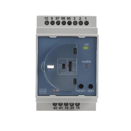
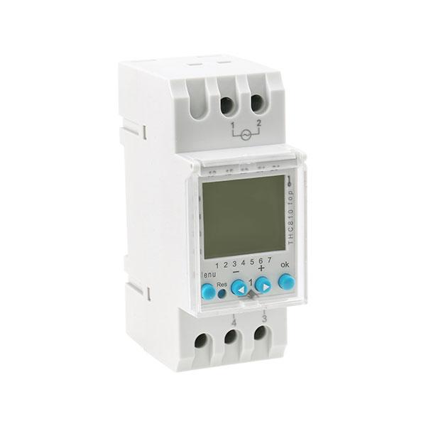
Time Relay:
- A relay with a time-delay function. When an input signal is applied or removed, its output contacts close or open only after a preset delay time.
- Time relays are commonly used in turnout starting circuits to achieve time control during turnout conversion.
Reasons for Using Relays in Railway Signaling Systems
- High Reliability:As a mature switching component, relays have a simple structure, stable performance, and can operate reliably for long periods under harsh railway environments (such as temperature variations, vibration, moisture, and dust). This is crucial for ensuring the safe operation of key equipment like signals, turnouts, and track circuits.
- High Safety:The "Fail-Safe" design principle of relays is fundamental to their application in railway signaling. When a relay fails (e.g., coil break, power loss), its contacts will automatically open due to gravity or spring force, causing the signaling system to enter the safest state (e.g., a signal showing red), thereby minimizing the risk of accidents.
- High Precision and Determinism:Relays have short and predictable response times, enabling precise switching control. In complex interlocking logic, relay operations are highly deterministic, ensuring the accuracy of signal control.
- Flexibility and Scalability:Relay logic circuits (relay interlocking) can implement complex control logic through different wiring methods. The system is easy to design, modify, and expand according to station layout and operational requirements.
- Good Electrical Isolation:The control circuit (coil side) and the controlled circuit (contact side) of a relay are completely electrically isolated, enhancing the system's immunity to interference and safety.