Transformer Component Lifespan | -Optimize Maintenance Schedules

The vulnerable components of a transformer and their replacement cycles must be determined comprehensively based on factors such as transformer type, operating environment, load conditions, and manufacturing processes.
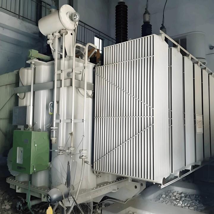
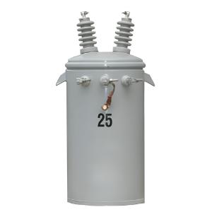
Common Vulnerable Components in Oil-Immersed Transformers
Oil-immersed transformers rely on insulating oil for heat dissipation and insulation. Their core components include the core, windings, insulation system, cooling system, and accessories. Vulnerable parts are primarily concentrated in the cooling system, insulation materials, seals, and auxiliary devices.
1. Cooling System Components
Submersible Oil Pumps: Drive the circulation of insulating oil for cooling. Long-term high load or frequent start-stop cycles can cause bearing wear and motor aging.
Replacement Cycle: Approximately 5–8 years under normal operation; may be shortened to 3–5 years under high operating temperatures or frequent overloads.Cooling Fans: Assist in heat dissipation. Motor bearings and fan blades are prone to failure due to dust accumulation or aging.
Replacement Cycle: 3–6 years.Radiators/Heat Dissipation Fins: Pipes in natural or forced oil circulation radiators may become clogged with oil sludge or develop leaks due to corrosion.
Replacement Cycle: No replacement needed if no leakage is evident; partial replacement may be required every 5–10 years if severe corrosion occurs.
2. Insulation Materials
Insulating Oil: Performs insulation and cooling functions. Performance degrades over time due to oxidation and intrusion of moisture or impurities.
Replacement Cycle: Test every 3–5 years under normal operation; filtration or replacement is required if parameters exceed limits; immediate replacement is necessary for severe degradation.Insulating Paper/Pressboard: Insulation between windings and core, primarily fails due to thermal or electrical aging.
Replacement Cycle: Design life is typically 20–30 years; may be prematurely retired by 5–10 years if operated at prolonged high temperatures.
3. Seals
Gaskets/Sealing Rings: Sealing components at tank, valve, and bushing locations. Prone to aging and cracking due to prolonged oil pressure and temperature fluctuations, leading to oil leaks.
Replacement Cycle: Inspect every 2–3 years if no leakage is evident; replace immediately upon detecting seepage.
4. On-Load Tap Changer (OLTC)
Core components include the diverter switch, selector switch, and electric drive mechanism. Frequent switching causes contact wear and oil degradation.
Replacement Cycle:Contacts: Mechanical life is approximately 1–2 million operations;
Insulating Oil: Test every 1–2 years; replace if degraded;
Entire Unit: Replace if switching exceeds design limits or if jamming or abnormal discharge occurs.
5. Other Accessories
Pressure Relief Valve: Protects against internal overpressure. The diaphragm may fail due to aging or frequent activation.
Replacement Cycle: Inspect every 5–8 years; replace diaphragm if aged.Gas Relay (Buchholz Relay): Detects internal faults. May fail due to oil sludge blockage or contact oxidation over time.
Replacement Cycle: Calibrate or replace every 3–5 years.
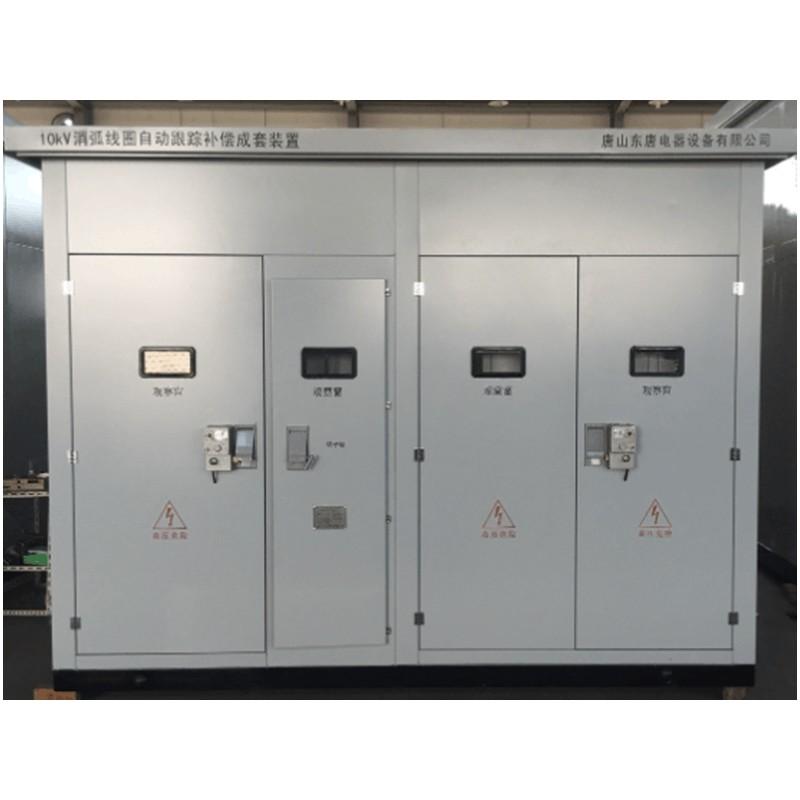
Common Vulnerable Components in Dry-Type Transformers
Dry-type transformers lack insulating oil and rely on air or resin insulation. Vulnerable components are primarily insulation materials, cooling fans, and connection parts.
1. Insulation Materials
Epoxy Resin/Glass Fiber: Used in winding encapsulation. Long-term high temperature or partial discharge can cause resin cracking and carbonization.
Replacement Cycle: Design life is 20–30 years; insulation defects may appear 5–10 years earlier under frequent overloads or high humidity.
2. Cooling Fans
Enhance heat dissipation. Motor bearings and blades are prone to aging.
Replacement Cycle: 3–5 years.
3. Winding Connection Terminals
High/low-voltage terminals may experience oxidation or loosening due to current heating, increasing contact resistance and overheating.
Replacement Cycle: Inspect and tighten every 3–5 years if no overheating; replace immediately if signs of burning are present.
4. Temperature Sensors/Thermostats
Monitor winding temperature. May give false alarms due to wiring aging or sensor failure over time.
Replacement Cycle: Calibrate every 2–3 years; replace when faulty.
Key Factors Affecting Replacement Cycles
Operating Environment: High temperature, humidity, dust, or corrosive gases accelerate insulation aging and metal corrosion.
Load Conditions: Prolonged overloading or frequent shock loads increase hot-spot temperatures and mechanical stress in windings.
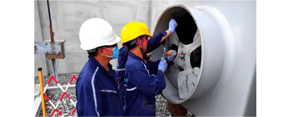
Maintenance Level: Regular oil chromatography analysis, infrared thermography, and cleaning of cooling systems can extend component life; neglecting inspections may allow hidden issues to escalate.
Replacement of vulnerable transformer components should be based on condition monitoring, combined with periodic testing and operational data, rather than strictly adhering to fixed intervals. For critical components, it is recommended to engage professional organizations for condition assessment to avoid unnecessary downtime or excessive maintenance.