Transformers experience various types of losses during operation, primarily categorized into two main types: copper losses and iron losses.
Copper Losses
Copper losses, also known as I²R losses, are caused by the electrical resistance of the transformer windings—typically made of copper. As current flows through the windings, energy is dissipated in the form of heat. These losses are proportional to the square of the load current (I²R), meaning they increase significantly with higher current levels.
To minimize copper losses:
Use thicker conductors or materials with higher electrical conductivity to reduce winding resistance.
Operate the transformer at or near its optimal load to avoid excessive current.
Improve overall operational efficiency by minimizing unnecessary loading and optimizing system design.
Iron Losses
Iron losses, or core losses, occur in the transformer’s magnetic core due to the alternating magnetic flux. These losses are independent of the load and remain relatively constant under normal operating conditions. Iron losses consist of two components:
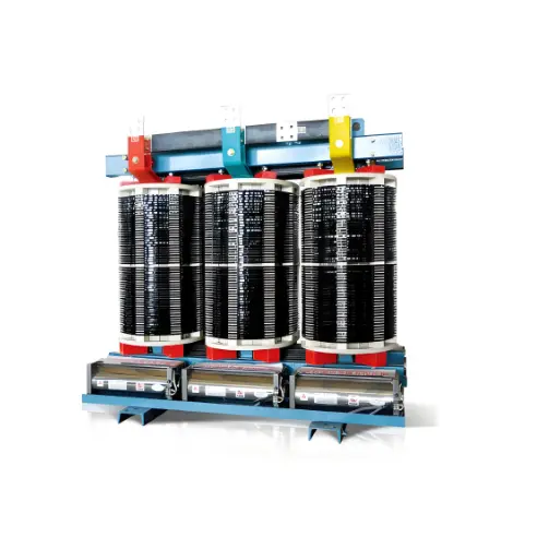
Hysteresis Loss: This results from the repeated magnetization and demagnetization of the core material under alternating current. Energy is lost as heat due to the internal friction of magnetic domains. Using core materials with a narrow hysteresis loop—such as grain-oriented silicon steel—can significantly reduce this loss.
Eddy Current Loss: Alternating magnetic fields induce circulating currents (eddy currents) within the core, leading to resistive heating. These losses are minimized by constructing the core from thin, insulated laminations oriented parallel to the magnetic flux, which restrict the path of eddy currents. Advanced core designs and high-resistivity materials also help reduce eddy current losses.
Strategies to Reduce Transformer Losses
Reducing transformer losses enhances efficiency, lowers operating costs, and extends equipment lifespan. Key measures include:
Select High-Efficiency Transformers: Modern high-efficiency transformers utilize advanced materials and optimized designs to minimize both copper and iron losses.
Optimize Design: Careful selection of core materials, winding configurations, and cooling systems can significantly reduce total losses.
Perform Regular Maintenance: Routine inspections and maintenance—such as cleaning windings, checking cooling systems, and maintaining oil quality in oil-filled transformers—ensure continued efficient operation.
Avoid Overloading: Excessive loading increases copper losses and thermal stress, accelerating insulation degradation and reducing reliability.
Match Capacity to Load: Properly sizing the transformer to the actual load demand prevents light-load inefficiencies and reduces no-load losses.
In conclusion, minimizing transformer losses is essential for energy conservation and reliable power system operation. Therefore, loss reduction should be a key consideration in the selection, design, and ongoing operation of transformers.