• Product
  • Suppliers
  • Manufacturers
  • Solutions
  • Free tools
  • Knowledges
  • Experts
  • Communities
Search


Campbell’s Bridge

Edwiin
Edwiin
Field: Power switch
China

Campbell Bridge: Definition and Function
Definition
The Campbell bridge is a specialized electrical bridge designed to measure unknown mutual inductance. Mutual inductance refers to the physical phenomenon where a change in the current flowing through one coil induces an electromotive force (emf) and, consequently, a current in a neighboring coil. This bridge is not only useful for determining mutual inductance values but can also be employed to measure frequency. It does so by adjusting the mutual inductance until a null point is achieved in the bridge circuit.
In electrical engineering, accurately measuring mutual inductance is crucial for understanding the interaction between different coils in circuits, such as in transformers, inductive coupling systems, and various electrical machinery. The Campbell bridge provides a precise and reliable method for these measurements. When used for frequency measurement, the null - point detection principle allows engineers to establish a relationship between the mutual inductance setting and the frequency of the electrical signal under test.
The following figure illustrates the concept of mutual inductance, which forms the foundation for the operation of the Campbell bridge.
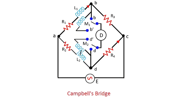
Let:

  • M1 represent the unknown mutual inductance

  • L1denote the self - inductance of the secondary of mutual inductance M1

  • M2signify the variable standard mutual inductance

  • L2 be the self - inductance of the secondary of mutual inductance M2

  • R1, R2, R3, R4 stand for non - inductive resistances

Achieving the balanced position of the Campbell bridge necessitates a two - step procedure:

Step 1: Initial Setup and First Balance Condition

The detector is initially connected between points ‘b’ and ‘d’. In this configuration, the circuit functions analogously to a simple self - inductance comme

  • First Balancing Step To bring the bridge to a balanced condition in the first stage, resistors R3 or R4, along with R1 and R2, are adjusted. This adjustment process fine - tunes the electrical parameters of the circuit, ensuring that the electrical potential differences across the relevant parts of the bridge are equalized, much like adjusting the weights on a balance scale to achieve equilibrium.

  • Second Balancing Step In the next phase, the detector is reconnected between points b' and d'. Building on the adjustments made in the first step, the variable standard mutual inductance M2 is then systematically varied. Through this process of varying M2 while maintaining the previously set resistor adjustments, the overall electrical configuration of the bridge is further optimized. Eventually, a balance point is reached, indicating that the bridge has achieved a state of equilibrium where the electrical signals in the circuit are in harmony, and accurate measurements of the unknown mutual inductance M1 can be made.

Give a tip and encourage the author!
Recommended
THD Measurement Error Standards for Power Systems
Error Tolerance of Total Harmonic Distortion (THD): A Comprehensive Analysis Based on Application Scenarios, Equipment Accuracy, and Industry StandardsThe acceptable error range for Total Harmonic Distortion (THD) must be evaluated based on specific application contexts, measurement equipment accuracy, and applicable industry standards. Below is a detailed analysis of key performance indicators in power systems, industrial equipment, and general measurement applications.1. Harmonic Error Standar
Edwiin
11/03/2025
Busbar-Side Grounding for 24kV Eco-Friendly RMUs: Why & How
Solid insulation assistance combined with dry air insulation is a development direction for 24 kV ring main units. By balancing insulation performance and compactness, the use of solid auxiliary insulation allows passing insulation tests without significantly increasing phase-to-phase or phase-to-ground dimensions. Encapsulation of the pole can address the insulation of the vacuum interrupter and its connected conductors.For the 24 kV outgoing busbar, with the phase spacing maintained at 110 mm,
Dyson
11/03/2025
How Vacuum Tech Replaces SF6 in Modern Ring Main Units
Ring main units (RMUs) are used in secondary power distribution, directly connecting to end-users such as residential communities, construction sites, commercial buildings, highways, etc.In a residential substation, the RMU introduces 12 kV medium voltage, which is then stepped down to 380 V low voltage through transformers. The low-voltage switchgear distributes electrical energy to various user units. For a 1250 kVA distribution transformer in a residential community, the medium-voltage ring m
James
11/03/2025
What Is THD? How It Affects Power Quality & Equipment
In the field of electrical engineering, the stability and reliability of power systems are of paramount importance. With the advancement of power electronics technology, the widespread use of nonlinear loads has led to an increasingly serious problem of harmonic distortion in power systems.Definition of THDTotal Harmonic Distortion (THD) is defined as the ratio of the root mean square (RMS) value of all harmonic components to the RMS value of the fundamental component in a periodic signal. It is
Encyclopedia
11/01/2025
Send inquiry
Download
Get the IEE Business Application
Use the IEE-Business app to find equipment, obtain solutions, connect with experts, and participate in industry collaboration anytime, anywhere—fully supporting the development of your power projects and business.