• Product
  • Suppliers
  • Manufacturers
  • Solutions
  • Free tools
  • Knowledges
  • Experts
  • Communities
Search


What is a Dual-Trace Oscilloscope? Definition, Working Principle & Modes Explained

Encyclopedia
Encyclopedia
Field: Encyclopedia
0
China

What is Dual Trace Oscilloscope?

Definition

A dual-trace oscilloscope uses a single electron beam to generate two separate traces, each deflected by an independent input source. To produce these two traces, it primarily employs two operating modes—alternate mode and chopped mode—controlled by a switch.

Purpose of a Dual-Trace Oscilloscope

When analyzing or studying multiple electronic circuits, comparing their voltage characteristics is often critical. While one could use multiple oscilloscopes for such comparisons, synchronizing the sweep triggering of each device is highly challenging. A dual-trace oscilloscope addresses this by generating two traces using a single electron beam, enabling convenient and accurate simultaneous analysis.

Block Diagram and Working Principle of a Dual-Trace Oscilloscope

The block diagram of a dual-trace oscilloscope is shown below:

Measurement.jpg

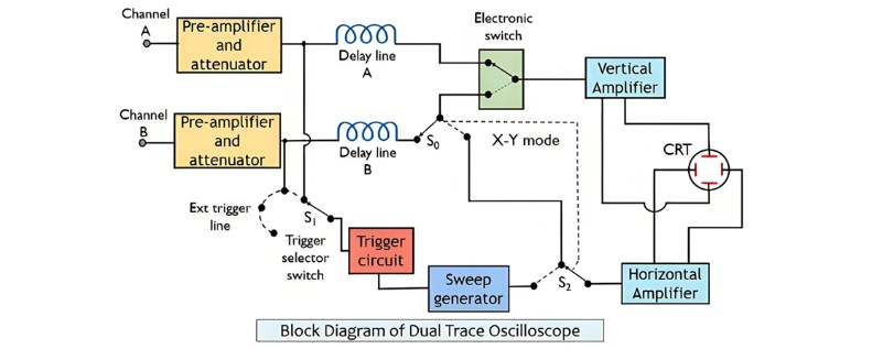
As shown in the figure above, the oscilloscope features two independent vertical input channels, labeled A and B.Each input is separately fed into a preamplifier and attenuator stage. The outputs from these two stages are then routed to an electronic switch, which allows only one channel’s input to pass through to the vertical amplifier at any given time.The circuit also includes a trigger selector switch, enabling triggering via either channel A, channel B, or an externally applied signal.

A horizontal amplifier supplies signals to the electronic switch, with the source determined by switches S0 and S2—either the sweep generator or channel B. This setup allows vertical signals from channel A and horizontal signals from channel B to be sent to the CRT, enabling X-Y mode operation for precise X-Y measurements.

The oscilloscope’s operating modes are selected via front-panel controls, allowing users to display traces from channel A alone, channel B alone, or both channels simultaneously. As previously noted, dual-trace oscilloscopes operate in two key modes:

Alternate Mode

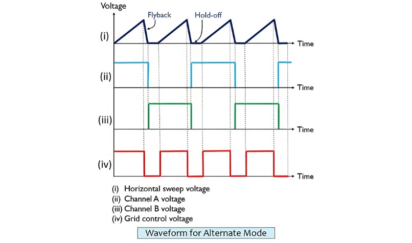
When alternate mode is activated, the electronic switch alternates between the two channels, switching at the start of each new sweep. The switching rate is synchronized with the sweep rate, ensuring each channel’s trace is displayed in separate sweeps: channel A’s trace appears in the first sweep, followed by channel B’s trace in the next.

Switching between channels occurs during the sweep flyback period, when the electron beam is invisible—preventing any visible disruption to the traces. This results in a complete sweep signal from one vertical channel being displayed, followed by a full sweep from the other channel in the subsequent cycle.

The waveform output of the oscilloscope operating in alternate mode is shown in the figure below:

Measurement..jpg

This mode preserves the correct phase relationship between signals from channels A and B. However, it has a drawback: the display shows the two signals as occurring at different times, even though they are actually simultaneous. Additionally, alternate mode is unsuitable for displaying low-frequency signals.

Chopped Mode

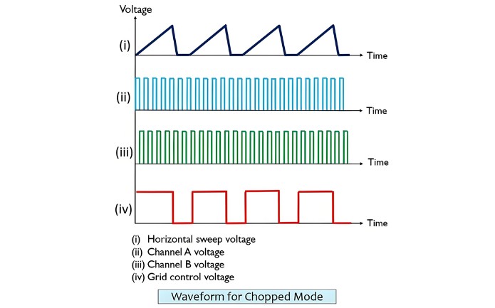
In chopped mode, the electronic switch rapidly alternates between the two channels multiple times during a single sweep. The switching is so fast that even tiny segments of each signal are displayed, creating the illusion of continuous traces for both channels.The waveform display in chopped mode is shown in the figure below:

Measurement...jpg

In chopped mode, the electronic switch operates in a free-running state at a high frequency (typically 100 kHz to 500 kHz), independent of the sweep generator’s frequency. This rapid switching ensures small segments of signals from both channels are continuously fed to the amplifier.

When the chopping rate exceeds the horizontal sweep rate, the chopped segments merge seamlessly on the CRT screen, reconstructing the original waveforms of channels A and B. Conversely, if the chopping rate is lower than the sweep rate, the display will show discontinuities—making alternate mode more suitable in such cases.Dual-trace oscilloscopes allow users to select the desired operating mode via a front-panel control.


Give a tip and encourage the author!
Recommended
THD Measurement Error Standards for Power Systems
Error Tolerance of Total Harmonic Distortion (THD): A Comprehensive Analysis Based on Application Scenarios, Equipment Accuracy, and Industry StandardsThe acceptable error range for Total Harmonic Distortion (THD) must be evaluated based on specific application contexts, measurement equipment accuracy, and applicable industry standards. Below is a detailed analysis of key performance indicators in power systems, industrial equipment, and general measurement applications.1. Harmonic Error Standar
Edwiin
11/03/2025
How Vacuum Tech Replaces SF6 in Modern Ring Main Units
Ring main units (RMUs) are used in secondary power distribution, directly connecting to end-users such as residential communities, construction sites, commercial buildings, highways, etc.In a residential substation, the RMU introduces 12 kV medium voltage, which is then stepped down to 380 V low voltage through transformers. The low-voltage switchgear distributes electrical energy to various user units. For a 1250 kVA distribution transformer in a residential community, the medium-voltage ring m
James
11/03/2025
Why Monitoring Accuracy Matters in Power Quality Systems
The Critical Role of Monitoring Accuracy in Power Quality Online DevicesThe measurement accuracy of online power quality monitoring devices is the core of the power system’s “perception capability,” directly determining the safety, economy, stability, and reliability of power supply to users. Inadequate accuracy leads to misjudgment, incorrect control, and flawed decision-making—potentially causing equipment damage, economic losses, or even grid failures. Conversely, high accuracy enables precis
Oliver Watts
10/30/2025
How Does Power Dispatching Ensure Grid Stability and Efficiency?
Electric Power Dispatching in Modern Power SystemsThe power system is a critical infrastructure of modern society, providing essential electrical energy for industrial, commercial, and residential use. As the core of power system operation and management, electric power dispatching aims to meet electricity demand while ensuring grid stability and economic efficiency.1. Basic Principles of Electric Power DispatchingThe fundamental principle of power dispatching is to balance supply and demand by
Echo
10/30/2025
Send inquiry
Download
Get the IEE Business Application
Use the IEE-Business app to find equipment, obtain solutions, connect with experts, and participate in industry collaboration anytime, anywhere—fully supporting the development of your power projects and business.