Why should electrical equipment be tested for insulation?

Purpose of Measuring Insulation Resistance
The primary reason for performing insulation testing on electrical equipment is to ensure public and personal safety. By conducting insulation tests between disconnected current-carrying conductors, grounding conductors, and conductors intended for grounding, the possibility of fires caused by short circuits can be eliminated.
Why Perform Insulation Testing?
-
Safety The most important reason for performing insulation testing is to ensure public and personal safety. By executing insulation tests on disconnected live conductors, grounding conductors, and conductors to be grounded, the risk of fires caused by short circuits can be eliminated.
-
Extending Equipment Life Insulation testing is also significant for protecting and extending the service life of electrical systems and motors. Periodic maintenance testing provides data for analysis and can predict potential system failures. Additionally, insulation testing is required to determine the cause of a failure when one occurs.
-
National Standards Requirement Both materials and electrical equipment must undergo insulation preventive tests according to corresponding national standards to verify the quality of manufactured electrical equipment and ensure that the equipment meets regulatory and safety standards.
Principle of Insulation Testing
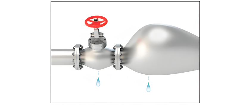
Insulation testing is analogous to finding leaks in a water pipe. Generally, high-pressure water is injected into the pipe to locate seepage. The pressurized water makes leak points easier to identify. In the electrical field, "pressure" refers to voltage. During insulation testing, a relatively high DC voltage is applied to the equipment under test to make potential leakage points more apparent.
An insulation resistance tester measures the leakage current under applied voltage and calculates the insulation resistance value using Ohm's Law. The design philosophy of such instruments is to apply and control test voltage in a "non-destructive" manner. Although the provided voltage is high, the current is very limited. This prevents secondary damage to the equipment due to poor insulation and ensures the safety of the operator.
Why Can't a Multimeter Be Used to Measure Insulation Resistance?
Although a multimeter can measure resistance, it cannot accurately indicate the condition of insulation. This is because a multimeter uses a 9V DC power source for measurement, which cannot provide the high voltage required for testing.
Selection of Insulation Test Voltage
According to the standard GB50150-2006 "Electrical Installation Engineering - Handover Test Standard for Electrical Equipment":
- For electrical equipment or circuits with an operating voltage below 100V, use a 250V test voltage.
- For electrical equipment or circuits with an operating voltage between 100V and 500V, use a 500V test voltage.
- For electrical equipment or circuits with an operating voltage between 500V and 3000V, use a 1000V test voltage.
- For electrical equipment or circuits with an operating voltage between 3000V and 10000V, use a 2500V test voltage.
- For electrical equipment or circuits with an operating voltage above 10000V, use a 5000V or 10000V test voltage.
Insulation Resistance Testing Procedure (using an insulation resistance tester as an example)
a. Turn off the equipment or system and disconnect it from all other circuits, switches, capacitors, brushes, surge arresters, and circuit breakers. b. Fully discharge the system under test to ground. c. Select the appropriate test voltage. d. Connect the leads. If the insulation resistance being measured is large, it is recommended to use shielded leads and add a grounding wire to prevent breakdown.
Test leads should be avoided from being tangled to reduce measurement errors. e. Start the test, read the instrument value after a period of time (usually one minute), and record the data and the ambient temperature at that time. f. At the end of the test, if the object under test is a capacitive device, fully discharge the device. Finally, remove the connecting leads.
Why Use Shielded Leads When Measuring Large Resistances?
When the insulation resistance being measured is very large, the measurement voltage is fixed, and the current through the conductor is relatively small, making it susceptible to external influences. Using shielded leads for testing, where the shielded lead is at the same potential as the negative (-) terminal, can prevent the accuracy of insulation resistance measurement from being reduced due to surface leakage or other unexpected current leakage. Additionally, during testing, apart from the two test probes, adding a grounding wire can prevent breakdown and ensure safety.
Insulation Testing Tools
Insulation resistance testing is performed using special testing instruments. The most commonly used instrument is the megohmmeter or insulation resistance tester, but other types of instruments can also be used to check the integrity of different insulation types.
- Megohmmeter (Hand-Cranked Type) A hand-cranked powered megohmmeter, known as a megohmmeter, originated in the 1950s and 1960s and is the earliest insulation resistance testing instrument. It comes in different specifications, such as 250V, 500V, and 1000V. It generates DC voltage by cranking the handle, features a pointer-type dial, and generally requires two people to operate: one to operate the megohmmeter and another to time and record data.
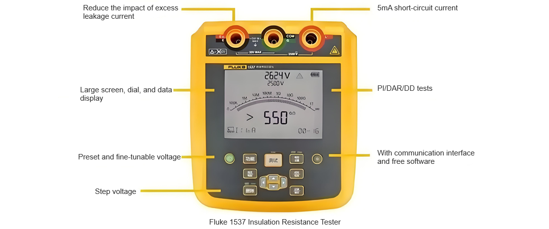
- Digital Insulation Resistance Tester A battery-powered megohmmeter with multiple adjustable test voltage ranges. The electronic display provides more accurate readings. It usually includes safety protection features such as automatic discharge and leakage current monitoring. With additional testing capabilities like multimeter functions, polarization index, and dielectric absorption ratio, its application range is broader. Its compact design allows a single engineer to complete all testing steps.
- Leakage Current Clamp Meter A leakage current clamp meter can be used to measure the insulation condition of equipment that cannot be de-energized. The magnetic fields generated by load currents cancel each other out. Any unbalanced current comes from current leaking from the conductor to earth or elsewhere. To measure this current, the leakage current clamp meter should be capable of detecting currents less than 0.1mA.

Precautions
- Do not connect the insulation tester to live conductors or energized equipment; ensure compliance with the manufacturer's instructions.
- Use open-type fuses, switches, and circuit breakers to turn off the equipment under test.
- Disconnect branch conductors, grounding conductors, and other equipment connected to the equipment under test.
- Ensure the disconnection of conductor capacitance before and after the test.
- Some equipment may have a discharge function.
- Check for leakage current in fuses, switches, and circuit breakers in de-energized circuits. Leakage current may cause contradictory or erroneous test readings.
- Do not use an insulation tester in environments containing hazardous or explosive gases, as the instrument may produce an arc if the insulation performance is compromised.
- Wear insulated rubber gloves when connecting test leads.


