Analog vs Digital Multimeter | Display, Accuracy & Working Principle Differences

We know that multimeters are essential electronic test instruments used to measure various electrical quantities such as voltage, current, and resistance. Multimeters are broadly categorized into two types: analog and digital. The key difference between analog and digital multimeters lies in how they display the measured values—analog multimeters use a moving pointer on a scale, while digital multimeters show readings numerically using digits. In this discussion, we will explore further distinctions between these two types.
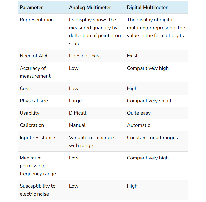
Comparison Chart
Definition of Analog Multimeter
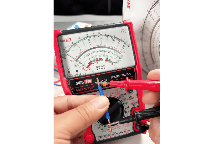
An analog multimeter is a type of multimeter that uses a needle or pointer moving across a calibrated scale to measure electrical parameters such as voltage, current, and resistance. When a measurement is taken, the result is displayed in analog form—specifically, by the deflection of a pointer that indicates a corresponding value on the scale. The position of the pointer on the scale directly reflects the magnitude of the measured quantity.
At its core, an analog multimeter consists of a moving-coil meter (also known as a galvanometer) with a needle attached to a rotating drum. This drum is positioned between the poles of a permanent magnet, and a fine wire coil is wound around it.
The fundamental operating principle is based on electromagnetic deflection. When the current to be measured flows through the coil, it generates a magnetic field. This field interacts with the fixed magnetic field of the permanent magnet, producing a torque that causes the coil and attached drum to rotate. As a result, the pointer deflects across the scale.
The movement of the pointer is regulated by small control springs connected to the drum. These springs provide a counteracting force that increases with deflection, eventually balancing the electromagnetic torque. This equilibrium determines the final position of the pointer, which thus indicates the measured value. The scale is calibrated accordingly to allow accurate reading of voltage, current, or resistance depending on the selected function.
Definition of Digital Multimeter
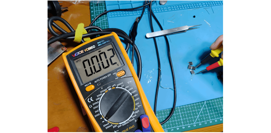
A digital multimeter (DMM) is a type of multimeter that displays measured electrical quantities numerically using a digital screen, typically an LCD or LED display. Since their introduction, digital multimeters have largely replaced analog models in many applications due to their numerous advantages, including higher accuracy, easier readability, enhanced input impedance, and additional features such as auto-ranging and data logging.
The core components of a digital multimeter include a display unit, signal conditioning circuits, an analog-to-digital converter (ADC), and encoding circuitry. The ADC plays a central role by converting the conditioned analog input signal into a digital value that can be processed and displayed.
For example, when measuring the resistance of a resistor, the DMM applies a known constant current from an internal current source through the resistor. The voltage drop across the resistor is then measured, amplified by a signal conditioning circuit, and fed into the ADC. The ADC converts this analog voltage into a digital signal, which is processed to calculate the resistance value. This result is then displayed numerically on the LCD screen, providing a clear and precise reading of the unknown resistance.
Conclusion
In summary, a multimeter—whether analog or digital—functions as a versatile, all-in-one instrument capable of performing the tasks of an ammeter, voltmeter, and ohmmeter. It can individually measure and display current, voltage, and resistance, consolidating the functionality of these three separate instruments into a single, portable device. This integration makes the multimeter an indispensable tool in electrical and electronic testing and troubleshooting.


