• Product
  • Suppliers
  • Manufacturers
  • Solutions
  • Free tools
  • Knowledges
  • Experts
  • Communities
Search


What is the function of a contactor in both AC and DC circuits?

Encyclopedia
Encyclopedia
Field: Encyclopedia
0
China

Role of Contactors in AC and DC Circuits

A contactor is an automatic switch used to frequently connect and disconnect circuits. It is widely applied in power systems. While the basic principle of contactors is similar in both AC and DC circuits, their roles can differ slightly. Below is a detailed explanation of the role of contactors in these two types of circuits:

Basic Principles of Contactors

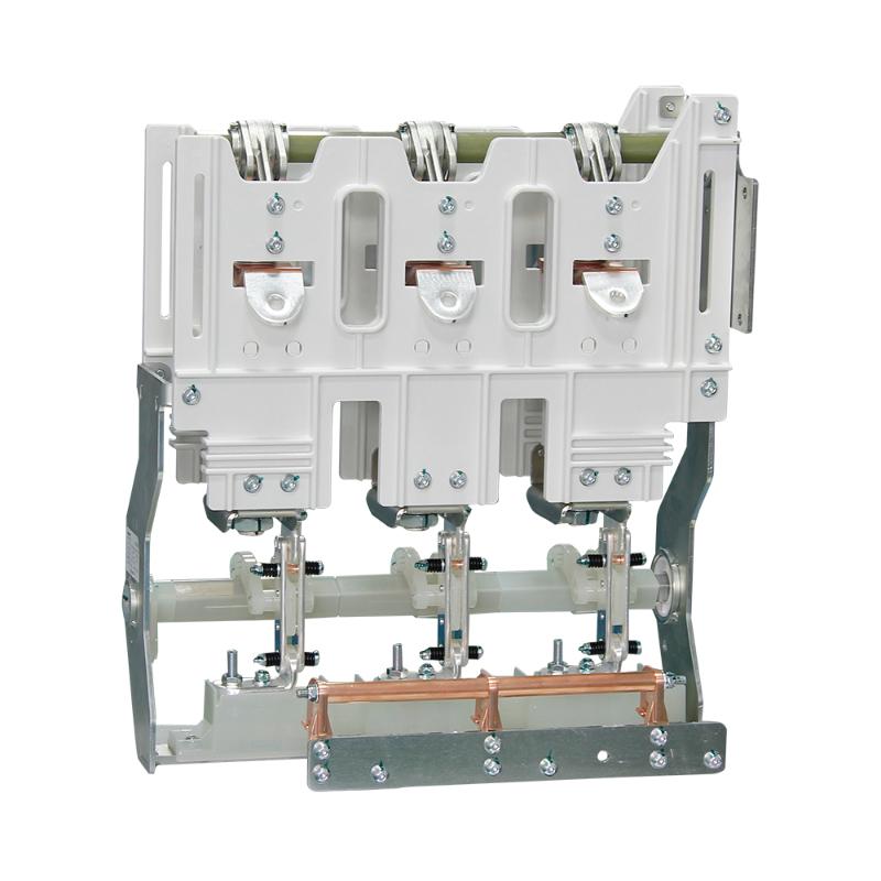
A contactor consists of three main parts:

  • Electromagnetic System: Includes the coil and core, used to generate electromagnetic force.

  • Contact System: Includes main contacts and auxiliary contacts, used to connect and disconnect the circuit.

  • Arc Suppression System: Used to extinguish the arc generated when the contacts open, protecting the contacts from damage.

Role in AC Circuits

Connecting and Disconnecting the Circuit:

  • When the coil is energized, the electromagnetic force attracts the armature, closing the main contacts and connecting the circuit.

  • When the coil is de-energized, the electromagnetic force disappears, and the spring returns the armature to its original position, opening the main contacts and disconnecting the circuit.

  • Contactors can frequently connect and disconnect AC circuits, making them suitable for controlling the start, stop, and speed regulation of motors.

Overload Protection:

Some contactors are equipped with overload protection features. When the current in the circuit exceeds a set value, the contactor automatically disconnects, protecting the circuit and equipment.

Remote Control:

Contactors can be controlled by remote signals (such as PLC output signals) to manage the connection and disconnection of the circuit, enabling automated control.

Arc Suppression:

In AC circuits, arcs are easier to extinguish because the AC current crosses zero points in each cycle. The arc suppression system of the contactor can quickly extinguish the arc, protecting the contacts.

Role in DC Circuits

Connecting and Disconnecting the Circuit:

  • The principle is the same as in AC circuits. When the coil is energized, the main contacts close, connecting the circuit; when the coil is de-energized, the main contacts open, disconnecting the circuit.

  • Contactors are used to control DC circuits, such as those for DC motors and battery charging systems.

Overload Protection:

DC contactors can also be equipped with overload protection features. When the current in the circuit exceeds a set value, the contactor automatically disconnects, protecting the circuit and equipment.

Remote Control:

DC contactors can also be controlled by remote signals to manage the connection and disconnection of the circuit, enabling automated control.

Arc Suppression:

In DC circuits, arcs are harder to extinguish because the DC current does not cross zero points. DC contactors typically have more robust arc suppression systems, such as magnetic blowout or grid arc extinction, to ensure rapid arc extinction and protect the contacts.

Summary

  • AC Circuits: Contactors are mainly used to frequently connect and disconnect AC circuits, providing overload protection and remote control functions. The arc suppression system in AC contactors is relatively simple because the zero-crossing nature of AC current helps naturally extinguish arcs.

  • DC Circuits: Contactors are also used to frequently connect and disconnect DC circuits, providing overload protection and remote control functions. The arc suppression system in DC contactors is more complex to address the challenge of arc extinction in DC circuits.

Understanding the role of contactors in AC and DC circuits helps in correctly selecting and using contactors to ensure the safety and reliable operation of circuits.

Give a tip and encourage the author!
Recommended
 Causes and Preventive Measures of Fire and Explosion in Oil Circuit Breakers
Causes and Preventive Measures of Fire and Explosion in Oil Circuit Breakers
Causes of Fire and Explosion in Oil Circuit Breakers When the oil level in an oil circuit breaker is too low, the oil layer covering the contacts becomes too thin. Under the effect of the electric arc, the oil decomposes and releases flammable gases. These gases accumulate in the space beneath the top cover, mixing with air to form an explosive mixture, which can ignite or explode under high temperature. If the oil level inside the tank is too high, the released gases have limited space to expan
Felix Spark
11/06/2025
LTB vs DTB vs GIS: HV Circuit Breaker Comparison
The basic meaning of a high-voltage circuit breaker is, simply put, that under normal conditions, it is used to open (interrupt, trip) and close (make, reclose) circuits, feeders, or specific loads—such as those connected to transformers or capacitor banks. When a fault occurs in the power system, protective relays activate the circuit breaker to interrupt either load current or short-circuit current, thereby ensuring the safe operation of the power system.A high-voltage circuit breaker is a typ
James
11/06/2025
What are the causes of failures in low-voltage switchgear circuit breakers themselves?
Based on years of field statistics on switchgear accidents, combined with analysis focusing on the circuit breaker itself, the main causes have been identified as: failure of operation mechanism; insulation faults; poor breaking and closing performance; and poor conductivity.1.Failure of Operation MechanismFailure of operation mechanism manifests as delayed operation or unintended operation. Since the most basic and important function of a high-voltage circuit breaker is to operate correctly and
Felix Spark
11/04/2025
THD Measurement Error Standards for Power Systems
Error Tolerance of Total Harmonic Distortion (THD): A Comprehensive Analysis Based on Application Scenarios, Equipment Accuracy, and Industry StandardsThe acceptable error range for Total Harmonic Distortion (THD) must be evaluated based on specific application contexts, measurement equipment accuracy, and applicable industry standards. Below is a detailed analysis of key performance indicators in power systems, industrial equipment, and general measurement applications.1. Harmonic Error Standar
Edwiin
11/03/2025
Related Products
Send inquiry
Download
Get the IEE Business Application
Use the IEE-Business app to find equipment, obtain solutions, connect with experts, and participate in industry collaboration anytime, anywhere—fully supporting the development of your power projects and business.