What is Arc Extinction Circuit Breaker?

When the current-carrying contacts of a circuit breaker separate, an arc forms and persists briefly after contact separation. This arc is hazardous due to the heat energy it generates, which can produce explosive forces.
A circuit breaker must extinguish the arc without damaging equipment or endangering personnel. The arc significantly influences the breaker’s performance. Interrupting a DC arc is inherently more challenging than an AC arc. In an AC arc, the current naturally reaches zero during each waveform cycle, causing the arc to vanish momentarily. This zero-crossing creates an opportunity to prevent arc restrike, leveraging the brief interval of current absence to deionize the gap and inhibit re-ignition.

The conductance of an arc is proportional to the electron density (ions per cubic centimeter), the square of the arc diameter, and the inverse of the arc length. For arc extinction, it is essential to reduce free electron density (ionization), shrink the arc diameter, and increase arc length.
Methods of Arc Extinction
There are two primary methods for arc extinction in circuit breakers:
High Resistance Method
Low Resistance (Zero Current Interruption) Method


-
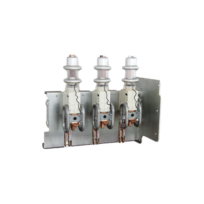
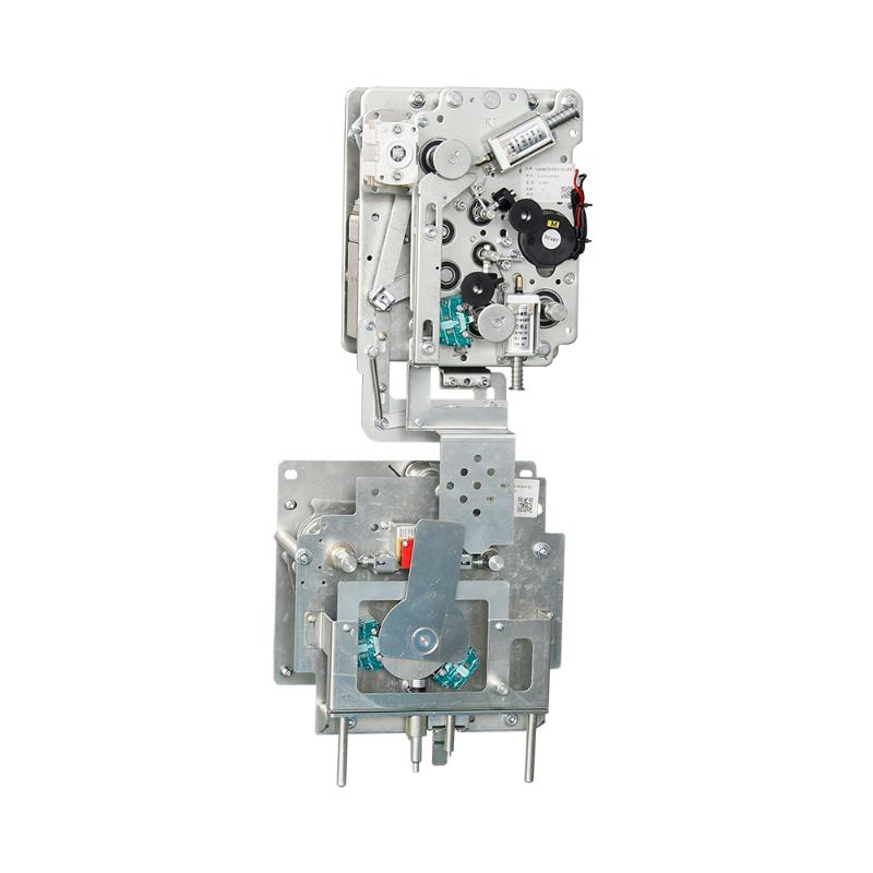
12KV 1250A SF6 gas filling cabinet electric spring operating mechanism circuit breaker mechanism
-
PremSeT Compact Vacuum Circuit Breaker Switchgear with Shielded Solid Insulation System (2SIS)

-
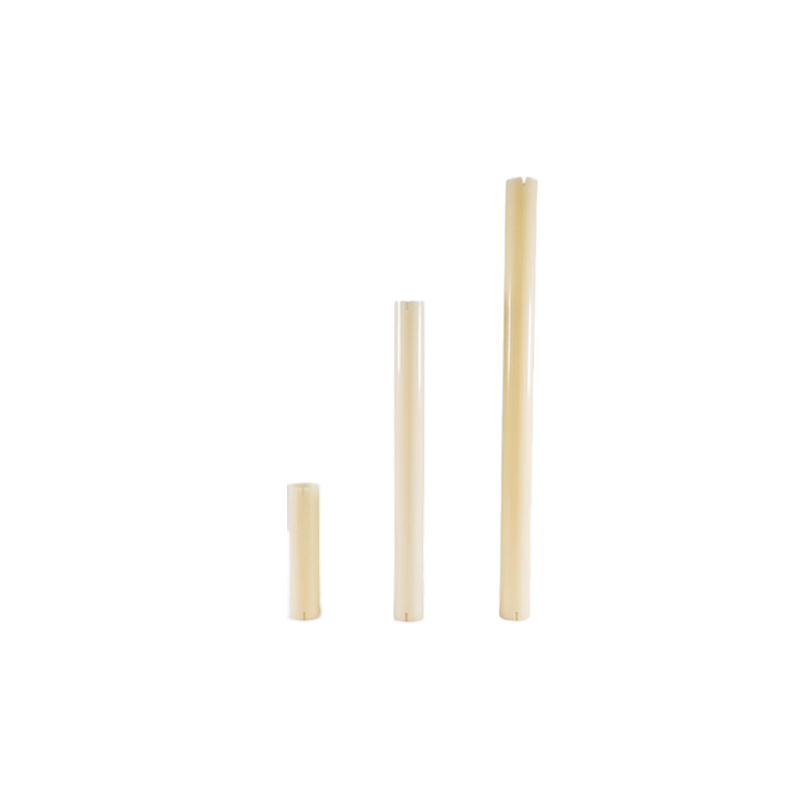
Insulation torsion bar for 252-1100kV GIS isolation switch
-
40.5kV SF6 gas-insulated high-voltage fuse combination load switch