How to Select a High-Voltage Circuit Breaker: Key Parameters & Expert Guide

Selecting a high-voltage circuit breaker is a critical task that directly impacts the safety, stability, and reliable operation of power systems. Below are the key technical specifications and considerations when selecting high-voltage circuit breakers—detailed, comprehensive, and professional.
Core Selection Process and Key Considerations
I. Basic Parameters Matching System Conditions (The Foundation)
This is the fundamental requirement—must fully match the characteristics of the installation point.
Rated Voltage (Uₙ)
Requirement: The breaker’s rated voltage must be greater than or equal to the maximum operating voltage at its installation location.
Example: In a 10kV system where the maximum operating voltage is 12kV, a 12kV rated voltage breaker should be selected.
Rated Current (Iₙ)
Requirement: The breaker’s rated current must be greater than or equal to the maximum continuous operating current of the circuit.
Calculation: Consider normal load current, overload capacity, potential future expansion, and include a safety margin. Avoid "undersized breaker for large load" or excessive investment.
Rated Frequency (fₙ)
Must match the power system frequency—50Hz in China.
II. Critical Short-Circuit Performance Parameters (The Capability Test)
These parameters measure the breaker’s interrupting and closing capabilities and must be selected based on system short-circuit calculations.
Rated Short-Circuit Interrupting Current (Iₖ)
Definition: The maximum RMS value of short-circuit current the breaker can reliably interrupt at rated voltage.
Requirement: This is the most critical parameter. The breaker’s rated interrupting current must be greater than or equal to the maximum prospective short-circuit current at the installation point (typically the three-phase short-circuit current calculated from system studies).
Note: Consider potential growth in system short-circuit capacity over the breaker’s service life.
Rated Short-Circuit Making Current (Iₘᶜ)
Definition: The maximum peak short-circuit current the breaker can successfully close onto.
Requirement: Typically 2.5 times the RMS value of the rated interrupting current (standard value). It must exceed the maximum prospective short-circuit current peak to withstand the enormous electrodynamic forces during closing.
Rated Short-Time Withstand Current (Iₖ) / Thermal Withstand Current
Definition: The RMS value of short-circuit current the breaker can withstand for a specified duration (e.g., 1s, 3s, 4s).
Requirement: Must be greater than or equal to the prospective short-circuit current RMS value at the installation point. Tests the breaker’s ability to withstand thermal effects of short-circuit currents.
Rated Peak Withstand Current (Iₚₖ) / Dynamic Withstand Current
Definition: The peak value of the first cycle of short-circuit current the breaker can endure.
Requirement: Must be greater than or equal to the prospective short-circuit current peak. Tests the mechanical strength of the breaker under electromagnetic forces during a short circuit.
III. Insulation and Environmental Protection Requirements
Insulation Medium Type (Core Technology Choice)
Advantages: Extremely high interrupting capacity, excellent performance.
Disadvantages: SF₆ is a potent greenhouse gas; requires high sealing integrity; leakage risk; relatively complex maintenance.
Application: Primarily used in high-voltage, high-capacity systems (≥35kV) or special environments (e.g., extremely cold regions).
Recommendation: In the 10–35kV range, unless special requirements exist, prefer vacuum breakers for their maturity and environmental benefits.
Advantages: Strong arc-quenching capability, long service life, compact size, low maintenance, no explosion risk, environmentally friendly. Suitable for frequent switching applications (e.g., arc furnaces, motor switching).
Application: The mainstream and preferred choice for 10–35kV voltage levels today.
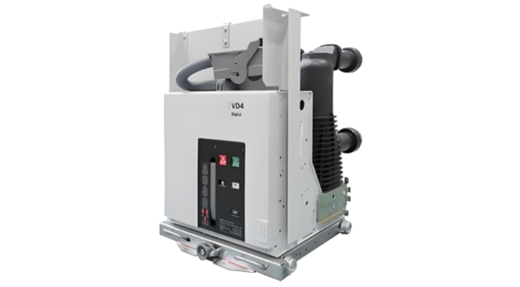
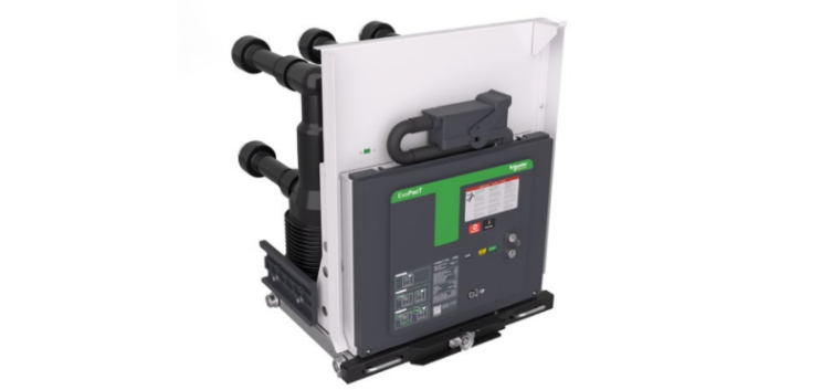
Vacuum Circuit Breaker (e.g., VS1, ZN63):
SF₆ (Sulfur Hexafluoride) Circuit Breaker:
External Insulation
Creepage Distance: Select bushings and insulators with sufficient creepage distance based on the site’s pollution level (I–IV), to prevent pollution flashover.
Condensation: For indoor switchgear in high-humidity or large temperature-differential environments prone to condensation, select breakers or switchgear equipped with heaters or anti-condensation devices.
IV. Mechanical Characteristics and Operating Mechanism
Operating Mechanism Type
Spring-Operated Mechanism: Most common, mature technology, high reliability, no external power source required. The preferred choice in most cases.
Permanent Magnet Actuator (PMA): Fewer parts, simpler structure, theoretically higher reliability and faster operation. However, field repair is difficult after failure—usually requires full replacement.
Electromagnetic Operating Mechanism: Used in older models; requires high-power DC supply and large closing current; gradually being phased out.
Mechanical and Electrical Endurance
Mechanical Endurance: Number of open-close operations without current (typically 10,000–30,000+ cycles).
Electrical Endurance: Number of normal interruptions at rated current (e.g., E2 class: 10,000 operations; C2 class: 100 short-circuit interruptions). For applications requiring frequent switching of capacitor banks, reactors, or motors, select breakers with high electrical endurance.
Breaking Time and Close-Open Time
For systems requiring coordination with relay protection or fast auto-reclosing, pay attention to the breaker’s total clearing time (from initiation of trip command to arc extinction).
V. Secondary Control and Auxiliary Functions
Control Voltage: Must match the substation’s DC power system (commonly DC 110V or DC 220V).
Auxiliary Contacts: Quantity must meet requirements for measurement, signaling, and interlocking.
Interlocking Functions: Must include reliable anti-pumping circuits, closing/tripping interlocks, etc., to ensure safety.
Smart Interface: Modern breakers often include intelligent controllers providing electrical parameter measurement, fault recording, condition monitoring, and support for communication protocols (e.g., IEC 61850), facilitating integration into integrated automation systems.
VI. Installation, Environment, and Brand/Service
Installation Type: Fixed or withdrawable (drawer-type)? Must match the switchgear model and structure.
Environmental Conditions: Consider altitude, ambient temperature, humidity. At high altitudes, breaker ratings must be derated.
Brand and After-Sales Service: Choose reputable brands with proven quality, and consider spare parts availability, technical support, and after-sales service.
VII. Summary: Selection Checklist
Confirm system parameters: system voltage, frequency, maximum operating current.
Calculate short-circuit current: obtain prospective RMS and peak short-circuit current at the installation point (provided by power system design).
Match breaker capabilities: ensure rated interrupting current, making current, and dynamic/thermal withstand currents all exceed calculated values.
Select type: prefer vacuum breakers for 10–35kV; confirm operating mechanism (spring mechanism preferred).
Verify external insulation: confirm creepage distance based on pollution level.
Consider special needs: frequent operation? Smart interface? Special environmental conditions?
Brand and commissioning: select reliable brands; during acceptance, focus on factory test reports (especially main circuit resistance and mechanical characteristics).
By following these steps, you can select a safe, suitable, and reliable high-voltage circuit breaker for your system. For critical applications, it is strongly recommended to jointly review and finalize the selection with professional electrical engineers or design institutes.