High- and Low-Voltage Electrical Room Safety Inspection: Strengthening Power System Security

High- and Low-Voltage Cable Lines and Cable Trays
Inspect cable trays for proper closure and secure rodent-proof sealing. High- and low-voltage cable trays should be intact and undamaged. Address any abnormalities promptly and maintain records.
Check for water seepage in cable trays entering switchrooms located in basements or low-lying areas.
Inspect cable pits and trenches for standing water or debris, and promptly drain water and remove contaminants if found.
Cables and cable terminations within pits and trenches should be clean and intact, with secure grounding connections and no signs of overheating or cracking.
Check that outdoor cable sheaths are intact and supports are secure.
All work teams and patrol personnel should be familiar with the routing and distribution of the cable lines under their responsibility.
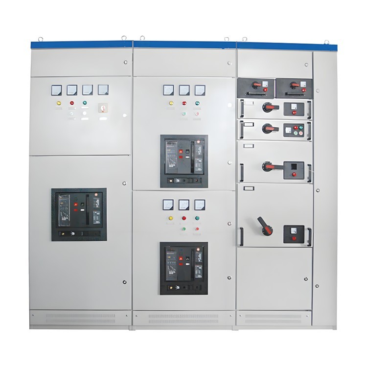
High-Voltage Switchgear and Ring Main Units
Indicators and live display devices on the switchgear panel should function normally. The operation mode selector switch and mechanical operating handle should be in the correct position, and the control and voltage circuit power switch indicators should be accurate.
The open/closed position indicators should match the actual operating status.
Meters and relays on the panel should operate normally, with no unusual sounds, odors, or overheating. The operation mode switch should normally be set to "remote control."
Internal lighting should be functional. Through the viewing window, internal equipment should appear normal. Insulators should be intact and undamaged.
There should be no discharge sounds, unusual odors, or irregular mechanical noises inside the cabinet. Temperature rise should be within normal limits.
The cabinet and busbar supports should show no overheating, deformation, or sagging. All enclosure screws should be present, tight, and free from rust. Grounding should be secure.
The vacuum interrupter of the vacuum circuit breaker should show no leakage. If the shield inside is made of glass, its surface should have a golden metallic luster, with no signs of oxidation or blackening. SF6 circuit breaker gas pressure should be normal. Porcelain components and insulating barriers should be intact, with no flashover marks. Connections and the breaker itself should show no signs of overheating. For enclosed switchgear that cannot be directly temperature-measured, use hand touch during inspection to detect overheating.
The circuit breaker operating mechanism should be intact. Check for dust accumulation on DC contactors and corrosion on secondary terminals.
Grounding should be reliable, and cabinet sealing and rodent/dust protection features should be effective.

Transformers
Monitor transformer temperature and ensure the temperature controller is functional. For oil-immersed self-cooled transformers, the top oil temperature should not exceed 95°C, and generally should not exceed 85°C. For forced-oil circulation air-cooled transformers, the top oil temperature should generally not exceed 75°C and must not exceed 85°C. For dry-type transformers, the winding temperature rise should not exceed 100°C (measured by resistance method). Operating temperature should generally stay below 110°C, with a maximum of 130°C.
Check for discoloration or overheating at the transformer body and high/low-voltage terminals. Listen for abnormal sounds or detect unusual odors.
Ensure the exterior is undamaged and free from vibration.
All connecting conductors and busbars should operate within normal temperature rise limits.
Low-Voltage Distribution Panels
Verify that connections of main busbars and branch circuit switches (knife switches, circuit breakers) are secure, and that terminal screws are tight. Confirm meter indications are correct.
Inspect all connection points in outgoing circuits for signs of overheating or discoloration.
During operation, check whether three-phase loads are balanced and three-phase voltages are equal. Monitor voltage drop in workshop loads to ensure it remains within specified limits.
Check for unusual sounds or odors inside distribution panels and electrical components.
For circuit breakers with arc chutes, ensure all three-phase arc chutes are present and undamaged.
Inspect the operation of circuit breakers and electromagnetic coils—ensure smooth engagement, no coil overheating, and no excessive noise.
Check that busbar insulation supports are undamaged and properly aligned, and that mounting screws are tight.
Keep electrical components clean and ensure grounding connections are secure and functional.
Ensure all doors and windows of the switchroom are intact and undamaged, cabinet doors are complete, and there is no water leakage from the roof during rain.
Capacitor Compensation Panels
Listen for internal discharge sounds in capacitors. Check for bulging, oil leakage, or damage to the casing.
Inspect porcelain components for cleanliness and any signs of discharge.
Ensure surge arresters are intact and grounding connections are secure.
Inspect series reactors and discharge transformers for damage.
Monitor capacitor room temperature. Winter minimum and summer maximum temperatures must comply with manufacturer specifications.
Check for broken external fuse links.
Monitor three-phase current readings for balance. Sudden fluctuations or increases should be investigated. Phase current imbalance should not exceed 10%.
Inspect discharge coils and three-phase discharge indicator lights for proper operation.
Check that oil level in oil-filled capacitors is within acceptable range.
Verify that the capacitor bank disconnect switch positions are correct.
Electrical Room Environment
Electrical rooms should have clear identification signs on doors, and door locks should be functional.
No Scrap Materials should be stored in the room. Equipment should be free from dust and oil buildup, and floors should be clean, dry, and free from debris. Maintain a tidy and clean environment.
Lighting and ventilation systems should be adequate and functional.
Fire protection equipment should be complete and effective.
Room temperature should not exceed 40°C, and relative humidity should be below 80%.
Drainage should be unobstructed, with no water seepage from roofs or underground areas. Rodent and insect protection systems should be fully operational.
Safety tools and protective equipment should be stored in designated, easily accessible locations.