• Product
  • Suppliers
  • Manufacturers
  • Solutions
  • Free tools
  • Knowledges
  • Experts
  • Communities
Search


Timing tests method in switchgears

Edwiin
Edwiin
Field: Power switch
China

Timing tests serve the purpose of determining the durations for operations such as opening (tripping), closing, close - opening, and reclosing. These time measurements are crucial for ensuring the safe and reliable operation of circuit breakers, thus being a key outcome of proper circuit breaker design.

The main contact times are verified after production, during commissioning, and while the circuit breaker is in - service as part of periodic maintenance. To conduct these tests, timing test devices need to be connected to both the coils and the main contacts of the circuit breaker.

Industry standards define the operation time as the interval from the moment the coil is energized until the main contacts open or close. A typical timing test device applies a voltage to the coils and utilizes an internal clock to measure the time elapsed until the state of the main contacts changes. Generally, there are two main methods employed to detect this state change:

  • Voltage divider method: This method measures the change in voltage.

  • Resistance threshold method: It measures the change in resistance.

However, these two methods are inapplicable when both sides of the circuit breaker are grounded, since the signal change becomes undetectable in such cases.

There are alternative test methods available:

  • Dynamic capacitance measurement (DCM)

  • Current sensor measurement (CSM)

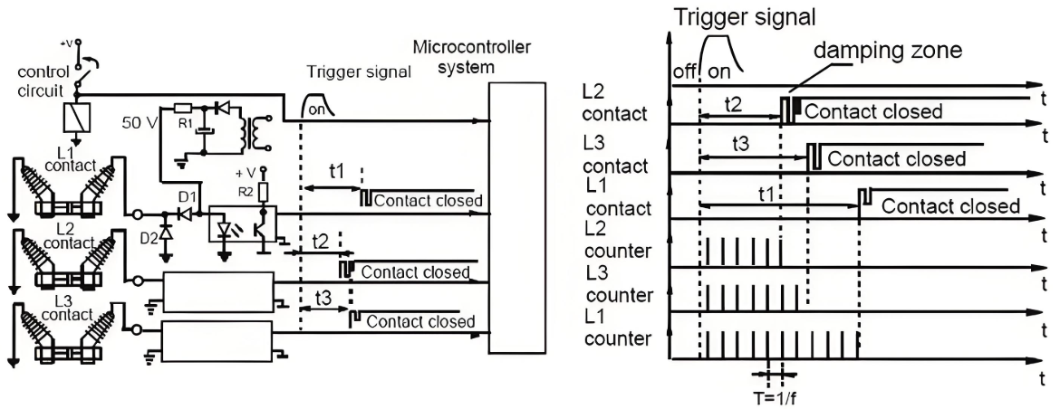
The accompanying photo depicts a timing test connection to switchgear (on the left) and time curves (on the right).

Give a tip and encourage the author!
Recommended
What are the causes of dielectric withstand failure in vacuum circuit breakers?
Causes of Dielectric Withstand Failure in Vacuum Circuit Breakers: Surface contamination: The product must be thoroughly cleaned before dielectric withstand testing to remove any dirt or contaminants.Dielectric withstand tests for circuit breakers include both power-frequency withstand voltage and lightning impulse withstand voltage. These tests must be performed separately for phase-to-phase and pole-to-pole (across the vacuum interrupter) configurations.Circuit breakers are recommended to be t
Felix Spark
11/04/2025
What are the causes of failures in low-voltage switchgear circuit breakers themselves?
Based on years of field statistics on switchgear accidents, combined with analysis focusing on the circuit breaker itself, the main causes have been identified as: failure of operation mechanism; insulation faults; poor breaking and closing performance; and poor conductivity.1.Failure of Operation MechanismFailure of operation mechanism manifests as delayed operation or unintended operation. Since the most basic and important function of a high-voltage circuit breaker is to operate correctly and
Felix Spark
11/04/2025
THD Measurement Error Standards for Power Systems
Error Tolerance of Total Harmonic Distortion (THD): A Comprehensive Analysis Based on Application Scenarios, Equipment Accuracy, and Industry StandardsThe acceptable error range for Total Harmonic Distortion (THD) must be evaluated based on specific application contexts, measurement equipment accuracy, and applicable industry standards. Below is a detailed analysis of key performance indicators in power systems, industrial equipment, and general measurement applications.1. Harmonic Error Standar
Edwiin
11/03/2025
Compact Air-Insulated RMUs for Retrofit & New Substations
Air-insulated ring main units (RMUs) are defined in contrast to compact gas-insulated RMUs. Early air-insulated RMUs used vacuum or puffer-type load switches from VEI, as well as gas-generating load switches. Later, with the widespread adoption of the SM6 series, it became the mainstream solution for air-insulated RMUs. Similar to other air-insulated RMUs, the key difference lies in replacing the load switch with an SF6-encapsulated type—where the three-position switch for load and grounding is
Echo
11/03/2025
Related Products
Send inquiry
Download
Get the IEE Business Application
Use the IEE-Business app to find equipment, obtain solutions, connect with experts, and participate in industry collaboration anytime, anywhere—fully supporting the development of your power projects and business.