Circuit breakers basic control circuit functions diagram

Circuit Breakers Control Circuit Functions Diagram Description
Circuit Breaker Main Contacts: These are not part of the control circuit. They serve as the primary conducting elements that open and close to interrupt or establish the main electrical circuit.
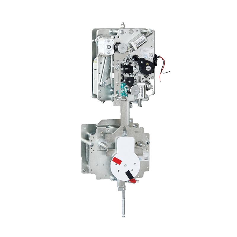
Mechanical Operating Mechanism: This mechanism releases the energy required to move the main contacts between the open and closed positions. It is also excluded from the control circuit proper. Its role is crucial in physically actuating the main contacts, which is essential for the circuit breaker's function of interrupting or allowing electrical current flow.
Energy Charging System: The energy charging system supplies energy to the operating mechanism. In systems with hydraulic, spring, or pneumatic energy storage, it typically consists of an electric motor, a motor - operated pump, or a compressor. This system ensures that the operating mechanism has the necessary power to perform its tasks, such as opening and closing the main contacts, thereby enabling the circuit breaker to operate effectively.
Density Monitor and Density Monitor Contacts: These devices play a vital role in supervising the insulation and/or arc - extinguishing media, which are typically SF6 or a mixed gas in modern circuit breakers. Commonly, temperature - compensated pressure switches are employed. They operate auxiliary relays to prevent the circuit breaker from tripping or closing if the SF6 gas density within the enclosure drops below critical levels. These switches and contacts fulfill two important functions:
Warning/Alarm Function: They provide a warning or alarm when the SF6 gas density in the enclosure decreases but remains above the lockout level. This early alert gives the operator sufficient time to address the issue before the circuit breaker locks out and loses its operational capabilities.
Interlocking/Prohibiting Function: When the SF6 gas density reaches the "lockout level," where safe operation is no longer possible, these components interlock or prohibit the operation of the circuit breaker. The operator usually has the option to configure the circuit breaker to either automatically trip and lockout when this level is reached (the "forced trip" option, which carries some safety risks) or to lockout in its current position.
Close Coil: The close coil is a solenoid device. When the circuit breaker receives a valid closing signal, the close coil is energized. This energization releases the mechanism, causing the main contacts of the circuit breaker to close. Once the circuit breaker reaches the closed position, auxiliary switch contacts in the closing circuit open, de - energizing the closing coils. Typically, there is only one closing coil in the control circuit to ensure a single, coordinated closing operation.
Open Coils: Open coils are also solenoid devices. Upon receiving a valid opening signal by the circuit breaker, they are energized. The energization of the open coils releases the mechanism, resulting in the opening of the main contacts of the circuit breaker. Once the circuit breaker reaches the open position, auxiliary switch contacts in the trip coil circuits open, de - energizing the trip coils. Usually, there are two trip coils that operate from independent power supplies. The operation of just one trip coil is sufficient to open the circuit breaker. The provision of two coils helps minimize the risk of a failure to trip, enhancing the reliability of the circuit - breaking process.
Position Auxiliary Switch: Driven by the operation of the circuit breaker, these contacts serve multiple purposes. They interrupt the current of the close and trip coils to de - energize them once the operation (closing or opening) is complete. Additionally, they are used for indicating and monitoring the position of the circuit breaker. They also play a role in interlocking control and protection operations at the bay or station level, preventing incorrect switching operations. These switches can be utilized in any function where the position of the circuit breaker is a critical parameter.
Anti - Pumping: The anti - pumping feature is designed to prevent a re - closing operation when a previous close command is still active while the circuit breaker has been opened. This mechanism stops the circuit breaker from repeatedly closing and opening, which could lead to damage and safety hazards. Typically, the close command energizes an anti - pumping relay via an auxiliary switch contact (a Normally Open (NO) contact). One contact of the anti - pumping relay interrupts the circuit to the close coil, while a second contact latches or "seals in" the anti - pumping relay until the close command is removed from the circuit.
Energy Limit Contact: The energy limit contacts are set to activate when the stored energy in the mechanism is depleted, either due to operation or losses. Usually, they trigger a motor to start, aiming to restore the energy of the mechanism to its normal operating level, such as re - compressing a spring or replenishing hydraulic/pneumatic pressure. For spring mechanisms, recharging typically occurs after every close operation, whereas other mechanism types may be able to perform several operations before recharging is needed. Pneumatic and hydraulic systems have a switch that monitors the pressure and energizes a compressor when the pressure falls below a critical level. Once the energy level is restored, a switch opens, stopping the motor. The motor is generally equipped with protection against thermal overload and a time - limit relay, which stops the motor (or a motor - operated pump or compressor) in case of a malfunction. The switches or contacts monitoring the stored energy perform the following functions:
Closing Lockout: They lock out the close operation if the circuit breaker lacks sufficient energy to close and re - open safely.
Opening Lockout: They lock out the open operation if the circuit breaker does not have enough energy to open safely. This is particularly relevant for hydraulic or pneumatic circuit breakers, although it may not apply in the same way to spring - operated breakers, where a successful closing charges the opening spring(s).
Charging Control: They control (start and stop) the charging circuit of the energy storage device (e.g., a spring).
Local/Remote Switch: This is a selector switch that allows the operator to disable remote control and operate the circuit breaker only locally. It serves as a safety feature to prevent remote operation of the circuit breaker during maintenance, ensuring the safety of maintenance personnel.
Disconnect/Fuse Element: These devices are used to cut off the power supply to the control system during maintenance work or when there is a fault in the control circuit. Disconnection is usually achieved through knife switches or removable fuses/links, which provide visual confirmation that the control circuit is open. They can also be locked in the open position to prevent unauthorized re - connection. In cases where short - circuit protection is required, Mini Circuit Breakers (MCB) can be used as an alternative to simple fuses.
Local Control and Indication: This function provides an indication of the circuit breaker's position and the status of the local/remote control facility. These indicators are mainly for maintenance purposes or emergency operations, depending on local safety regulations, enabling personnel to quickly assess the circuit breaker's condition.
Pole Discrepancy/Pole Disagreement Circuit: For Independent Pole Operation (IPO) circuit breakers, where each phase has its own operating mechanism, it is possible for one phase of the circuit breaker to be in a different position (open or closed) compared to the other phases. This situation, known as pole discrepancy or pole disagreement, can lead to an unsymmetrical primary current. When a pole discrepancy occurs, auxiliary switch contacts in each phase are used to energize a time - delay relay. If the discrepancy persists after the preset time delay (usually between 1.5 to 5 seconds, depending on specific grid conditions and the allowable duration of asymmetric primary circuit operation, which should be longer than the one - phase auto - reclose time and shorter than the negative phase sequence protection of generation), an attempt will be made to trip all phases of the circuit breaker. If the pole discrepancy was due to a failure to close one pole, the trip is likely to succeed. However, if the initial discrepancy was due to a failure to open, the failed pole may not respond to subsequent opening commands, and opening other circuit breakers may be necessary.
Heating: Space heaters are commonly installed in each of the operating mechanism and control housings. Their purpose is to reduce condensation, which can cause corrosion and malfunctions in the equipment, thereby ensuring the reliable operation of the circuit breaker components.