• Product
  • Suppliers
  • Manufacturers
  • Solutions
  • Free tools
  • Knowledges
  • Experts
  • Communities
Search


Digital Fault Recorders (DFR) monitoring method for switchgears

Edwiin
Edwiin
Field: Power switch
China

Digital Fault Recorder (DFR) System for Circuit Breaker Monitoring

The Digital Fault Recorder (DFR) system is designed to record current and voltage oscillograms during every circuit breaker switching operation. It captures data for a time period of approximately three to five seconds around the moment of switching. Once collected, this data is transmitted to a server, where specialized software conducts in - depth analysis. This monitoring approach can be implemented in any switchgear equipped with a DFR, provided that the DFR can be properly programmed to trigger and store data from each switching event.

The information gathered by the DFR system can be archived to document the following critical aspects:

  • Electrical Phenomena: The occurrence of prestrikes, re - ignitions, and restrikes during switching operations, which are essential for understanding the electrical behavior and potential stress on the circuit breaker.

  • Timing Parameters: Key operation timing metrics that help in evaluating the performance and coordination of the circuit breaker within the electrical system.

  • Operation Classification: The number of operations categorized as fault - related, normal load - carrying, or no - load, offering insights into the operational history and usage patterns of the circuit breaker.

  • Arcing Energy: The cumulative amount of arcing energy, represented by I^2T, which is crucial for assessing the wear and tear on the circuit breaker contacts.

  • Resistor Functionality: The proper functioning of the pre - insertion resistor, ensuring its correct operation during switching sequences.

When the protection signal is directly available in the DFR or can be accurately correlated by the analysis software, the current and voltage oscillograms enable the precise evaluation of the arcing time and the make time per pole. This detailed information is invaluable for assessing the performance and reliability of the circuit breaker.

However, several factors can impose limitations on this monitoring method. These include the characteristics of current transformers (CTs), voltage transformers (VTs), and other sensors; the potential saturation of CTs; the sampling rate (ranging from 1 kHz to 20 kHz); the network configuration; the type of electrical load; the design and specifications of the circuit breaker; as well as the storage capacity of the DFR and the format of the stored data.

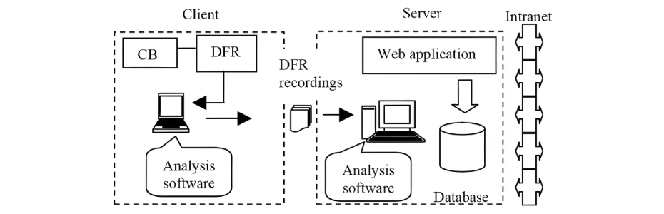
The following picture illustrates the system architecture of the circuit breaker monitoring system that employs the DFR method.

Give a tip and encourage the author!
Recommended
What are the causes of failures in low-voltage switchgear circuit breakers themselves?
Based on years of field statistics on switchgear accidents, combined with analysis focusing on the circuit breaker itself, the main causes have been identified as: failure of operation mechanism; insulation faults; poor breaking and closing performance; and poor conductivity.1.Failure of Operation MechanismFailure of operation mechanism manifests as delayed operation or unintended operation. Since the most basic and important function of a high-voltage circuit breaker is to operate correctly and
Felix Spark
11/04/2025
THD Measurement Error Standards for Power Systems
Error Tolerance of Total Harmonic Distortion (THD): A Comprehensive Analysis Based on Application Scenarios, Equipment Accuracy, and Industry StandardsThe acceptable error range for Total Harmonic Distortion (THD) must be evaluated based on specific application contexts, measurement equipment accuracy, and applicable industry standards. Below is a detailed analysis of key performance indicators in power systems, industrial equipment, and general measurement applications.1. Harmonic Error Standar
Edwiin
11/03/2025
Compact Air-Insulated RMUs for Retrofit & New Substations
Air-insulated ring main units (RMUs) are defined in contrast to compact gas-insulated RMUs. Early air-insulated RMUs used vacuum or puffer-type load switches from VEI, as well as gas-generating load switches. Later, with the widespread adoption of the SM6 series, it became the mainstream solution for air-insulated RMUs. Similar to other air-insulated RMUs, the key difference lies in replacing the load switch with an SF6-encapsulated type—where the three-position switch for load and grounding is
Echo
11/03/2025
Climate-Neutral 24kV Switchgear for Sustainable Grids | Nu1
Expected service life of 30–40 years, front access, compact design equivalent to SF6-GIS, no SF6 gas handling – climate-friendly, 100% dry air insulation. The Nu1 switchgear is metal-enclosed, gas-insulated, featuring a withdrawable circuit breaker design, and has been type-tested according to relevant standards, approved by the internationally recognized STL laboratory.Compliance Standards Switchgear: IEC 62271-1 High-voltage switchgear and controlgear – Part 1: Common specifications for altern
Edwiin
11/03/2025
Related Products
Send inquiry
Download
Get the IEE Business Application
Use the IEE-Business app to find equipment, obtain solutions, connect with experts, and participate in industry collaboration anytime, anywhere—fully supporting the development of your power projects and business.