• Product
  • Suppliers
  • Manufacturers
  • Solutions
  • Free tools
  • Knowledges
  • Experts
  • Communities
Search


Generator Synchronization

Edwiin
Edwiin
Field: Power switch
China

A stationary generator must never be connected to live busbars, as the induced electromotive force (EMF) is zero at standstill, which would cause a short circuit. The synchronization procedure and the equipment used for checking it are identical whether one alternator is to be connected in parallel with another alternator or an alternator is to be connected to an infinite bus.

Synchronisation via Synchronising Lamps

A set of three synchronizing lamps can be employed to verify the conditions for paralleling or synchronizing an incoming machine with another. The dark lamp method—used in conjunction with a voltmeter for synchronization—is illustrated below. This approach is suitable for low-power machines.

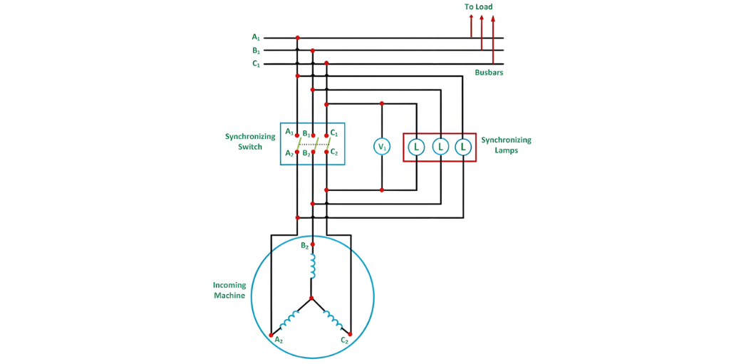
Synchronization Process Using Synchronizing Lamps

  • Prime Mover and Voltage Adjustment

    • Start the prime mover of the incoming machine and accelerate it to near its rated speed.

    • Adjust the field current of the incoming machine until its output voltage matches the bus voltage.

  • Frequency and Phase Detection

    • The three synchronizing lamps will flicker at a rate proportional to the frequency difference between the incoming machine and the bus.

    • Phase Sequence Check: If all lamps glow and dim simultaneously, the phase connections are correct. If not, the phase sequence is misaligned.

  • Corrective Actions and Switch Closure

    • To rectify phase sequence, interchange any two line leads of the incoming machine.

    • Fine-tune the incoming machine’s frequency until the lamps flicker at a rate of less than one dark period per second.

    • After final voltage adjustment, close the synchronizing switch at the midpoint of the dark period to minimize voltage discrepancy.

Advantages of the Dark Lamp Method

  • Cost-efficient compared to other synchronization techniques.

  • Enables straightforward verification of correct phase sequence.

Disadvantages of the Dark Lamp Method

  • Lamps appear dark at approximately 50% of their rated voltage, risking switch closure during residual phase differences.

  • Frequent voltage fluctuations may cause filament burnout.

  • Flicker behavior does not indicate whether the incoming frequency is higher or lower than the bus frequency.

Three Bright Lamp Method

  • Connection Scheme: Lamps are cross-connected across phases (e.g., A1-B2, B1-C2, C1-A2).

  • Synchronization Cue: If all lamps brighten and dim in unison, the phase sequence is correct.

  • Optimal Switching: Close the switch at the peak of the bright period.

Two Bright One Dark Lamp Method

  • Connection Configuration: One lamp is connected between corresponding phases (e.g., A1-A2), while the other two are cross-connected (e.g., B1-C2, C1-B2), as illustrated below.

  • Phase Indication: The correct phase sequence is confirmed when one lamp remains dark while the other two alternate between brightness and darkness.

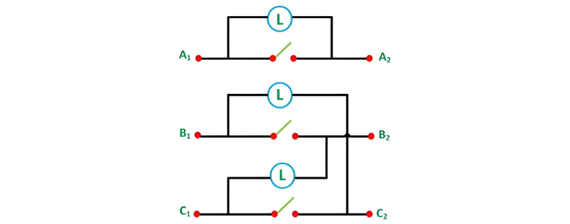
Connection Configuration and Synchronization Steps

In this setup, A1 is connected to A2, B1 to C2, and C1 to B2. The prime mover of the incoming machine is started and accelerated to its rated speed. The excitation of the incoming machine is adjusted such that the induced voltages EA1, EB2, EC3 match the busbar voltages VA1, VB1, VC1. The corresponding diagram is illustrated below.

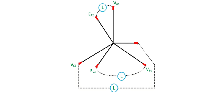
Optimal Switch Closure and Phase Sequence Verification

The ideal moment to close the synchronizing switch occurs when the directly connected lamp (A1-A2) is fully dark while the cross-connected lamps (B1-C2, C1-B2) are equally bright. If the phase sequence is incorrect, this condition will not be met, and all lamps will either remain dark or flicker out of sync.

To correct the phase sequence, swap any two line connections of the incoming machine. Since the dark range of incandescent lamps spans a significant voltage interval (typically 40-60% of rated voltage), a voltmeter (V1) is connected across the directly connected lamp. The switch should be closed when the voltmeter reads zero, indicating minimal voltage difference between the incoming machine and the busbar.

Operational Modes and Automation

Once synchronized, the incoming machine "floats" on the busbar and can begin delivering power as a generator. If the prime mover is disengaged while connected, the machine will operate as a motor, drawing power from the grid.

  • Small-Scale Synchronization: In low-power applications, three-lamp methods are often supplemented with a synchroscope to verify frequency matching.

  • Large-Scale Automation: For high-capacity generators in power stations, computerized systems execute the entire synchronization process autonomously, ensuring precision and safety.

Give a tip and encourage the author!
Recommended
 Causes and Preventive Measures of Fire and Explosion in Oil Circuit Breakers
Causes and Preventive Measures of Fire and Explosion in Oil Circuit Breakers
Causes of Fire and Explosion in Oil Circuit Breakers When the oil level in an oil circuit breaker is too low, the oil layer covering the contacts becomes too thin. Under the effect of the electric arc, the oil decomposes and releases flammable gases. These gases accumulate in the space beneath the top cover, mixing with air to form an explosive mixture, which can ignite or explode under high temperature. If the oil level inside the tank is too high, the released gases have limited space to expan
Felix Spark
11/06/2025
THD Measurement Error Standards for Power Systems
Error Tolerance of Total Harmonic Distortion (THD): A Comprehensive Analysis Based on Application Scenarios, Equipment Accuracy, and Industry StandardsThe acceptable error range for Total Harmonic Distortion (THD) must be evaluated based on specific application contexts, measurement equipment accuracy, and applicable industry standards. Below is a detailed analysis of key performance indicators in power systems, industrial equipment, and general measurement applications.1. Harmonic Error Standar
Edwiin
11/03/2025
Busbar-Side Grounding for 24kV Eco-Friendly RMUs: Why & How
Solid insulation assistance combined with dry air insulation is a development direction for 24 kV ring main units. By balancing insulation performance and compactness, the use of solid auxiliary insulation allows passing insulation tests without significantly increasing phase-to-phase or phase-to-ground dimensions. Encapsulation of the pole can address the insulation of the vacuum interrupter and its connected conductors.For the 24 kV outgoing busbar, with the phase spacing maintained at 110 mm,
Dyson
11/03/2025
How Vacuum Tech Replaces SF6 in Modern Ring Main Units
Ring main units (RMUs) are used in secondary power distribution, directly connecting to end-users such as residential communities, construction sites, commercial buildings, highways, etc.In a residential substation, the RMU introduces 12 kV medium voltage, which is then stepped down to 380 V low voltage through transformers. The low-voltage switchgear distributes electrical energy to various user units. For a 1250 kVA distribution transformer in a residential community, the medium-voltage ring m
James
11/03/2025
Send inquiry
Download
Get the IEE Business Application
Use the IEE-Business app to find equipment, obtain solutions, connect with experts, and participate in industry collaboration anytime, anywhere—fully supporting the development of your power projects and business.