General Requirements for Power Transformer Cooling Systems
All cooling devices shall be installed in accordance with the manufacturer's specifications;
The cooling system with forced oil circulation must have two independent power supplies with automatic switching capability. When the working power supply fails, the standby power supply shall be automatically activated while emitting audible and visual signals;
For transformers with forced oil circulation, when a faulty cooler is disconnected, audible and visual signals shall be emitted, and the standby cooler shall be automatically (manually for water cooling) activated;
The auxiliary motors of fans, water pumps, and oil pumps shall have overload, short-circuit, and phase-loss protection; there shall be devices to monitor the rotation direction of oil pump motors;
For water-cooled heat exchangers, the oil pump shall be installed on the oil inlet side of the cooler, ensuring that the oil pressure in the cooler is greater than the water pressure by approximately 0.05MPa under all conditions (except where otherwise specified by the manufacturer). A drain plug shall be provided on the water outlet side of the cooler;
For transformers with forced oil circulation water cooling, a check valve shall be installed at the outlet of each submersible oil pump in the coolers;
Transformers with forced oil circulation cooling shall be capable of controlling the switching on and off of coolers based on temperature and/or load.
Function of Transformer Coolers
When a temperature difference exists between the upper and lower oil in a transformer, oil convection is formed through the cooler. After being cooled in the cooler, the oil flows back to the tank, thereby reducing the transformer's temperature.
Cooling Methods for Transformer Coolers
Oil-immersed natural air cooling method;
Oil-immersed forced air cooling method;
Forced oil circulation water cooling method;
Forced oil circulation air cooling method;
Forced oil circulation directed cooling method.
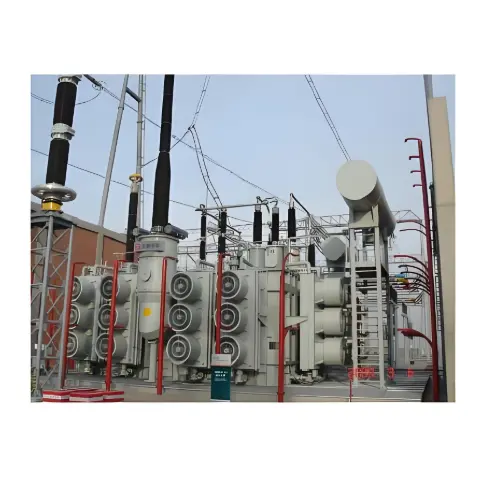
In 500kV substations, large transformers generally adopt the forced oil circulation air cooling method, while extra-large transformers use the forced oil circulation directed cooling method.
Working Principle of Transformer Coolers
Traditional power transformers use manually controlled fans, with each transformer typically having 6 groups of air-cooled motors that need to be controlled. Each group of fans relies on thermal relays for operation, with the fan power circuits controlled through contactors. The fans start and stop based on logical judgments made from measurements of the transformer's oil temperature and overload conditions.
The mechanical contacts are primarily driven by manual mechanical contacts. Such traditional control relies solely on manual operation. However, its biggest drawback is that all fans must start and stop simultaneously, generating significant inrush currents during startup that often damage components in the circuit. When temperatures range between 45 to 55 degrees Celsius, all fans typically operate at full capacity, resulting in enormous energy waste and creating significant difficulties for equipment maintenance.
Conventional cooling control systems mainly employ components such as relays, thermal relays, and various contact-based logic circuit control systems, with highly complex control logic. During actual operation, contactors frequently burn out due to repeated contact and separation of contacts. Additionally, the fans lack necessary protections such as overload, phase loss, and overcurrent protection, reducing operational reliability and increasing operating costs during actual operation.

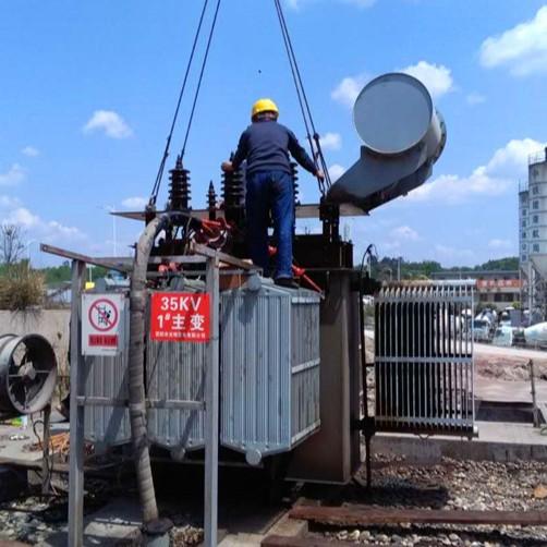
Components of Forced Oil Forced Air Cooled Transformer Coolers
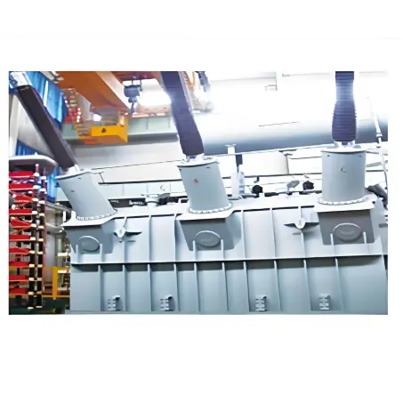
The cooler consists of heat exchangers, fans, motors, air ducts, oil pumps, and oil flow indicators. The cooling fans are used to exhaust the hot air emitted from the heat exchangers. The oil pump is installed at the bottom of the cooler to circulate the oil from the top of the heat exchanger downward. The oil flow indicator is installed at a conspicuous position at the lower part of the cooler to facilitate operators in observing the operational status of the oil pump.
Functions of Transformer Tanks and Cooling Devices
The transformer tank serves as the outer casing of the transformer, containing the iron core, windings, and transformer oil, while also providing a certain degree of heat dissipation.
The function of the transformer cooling device is to create oil circulation through the radiator when a temperature difference exists in the upper oil layer of the transformer. This allows the oil to be cooled in the radiator before flowing back into the tank, effectively reducing the transformer oil temperature. To enhance cooling efficiency, measures such as air cooling, forced oil forced air cooling, or forced oil water cooling can be adopted.