Large Power Transformer Installation & Handling Procedures Guide

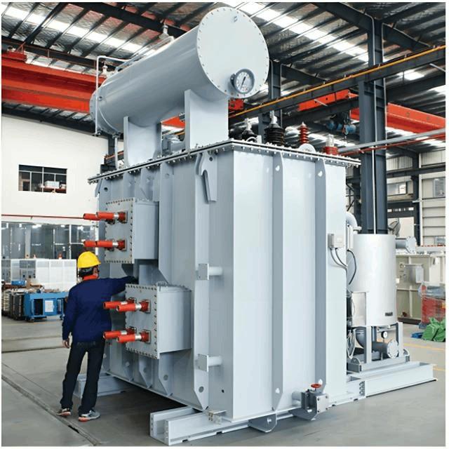
1. Mechanical Direct Towing of Large Power Transformers
When large power transformers are transported using mechanical direct towing, the following work shall be properly completed:
- Investigate the structure, width, gradient, slope, inclination, turning angles, and load-bearing capacity of roads, bridges, culverts, ditches, etc. along the route; reinforce them when necessary.
- Survey overhead obstacles along the route such as power lines and communication lines.
- During loading, unloading, and transportation of transformers, severe shock or vibration shall be avoided. When using mechanical traction, the traction force point should be below the equipment's center of gravity. The transportation inclination angle shall not exceed 15° (except for dry-type transformers).
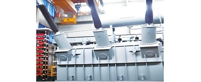
- When hoisting bell-type transformers as a whole unit, the steel wire rope shall be attached to the dedicated lifting lugs on the lower oil tank specifically designed for whole-unit hoisting. The rope must be guided through the corresponding lugs on the upper bell section to prevent the transformer from tipping over.
- When jacking up a transformer with hydraulic jacks, place the jacks on the designated support positions on the oil tank. The lifting operations should be coordinated with uniform force distribution at all points.
2. Protection During Transportation
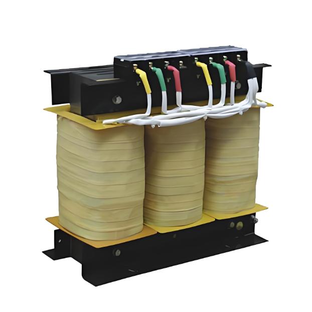
Dry-type transformers shall be protected against rain during transportation.
2.1 Visual Inspection Upon Arrival
After arrival at the site, transformers shall be promptly inspected for the following external conditions:
- The oil tank and all accessories shall be complete, without rust or mechanical damage.
- All connecting bolts on the tank cover or bell flange and sealing plates shall be complete, properly tightened, and free from oil leakage.
- Porcelain bushings shall be intact without damage.
- For dry-type transformers, the epoxy casting shall have no cracks or damage; the insulation wrapping of leads shall be intact and securely fixed.
- For transformers transported under gas pressure, the oil tank shall maintain positive pressure at 0.01-0.03 MPa.
3. Proper Storage Requirements
After arrival at the site, transformers shall be properly stored according to the following requirements:
- The bottom of the main body, cooling devices, etc., shall be elevated and leveled, protected from water flooding. Dry-type transformers shall be placed in dry indoor areas.
- Radiators, oil purifiers, pressure relief devices, etc., shall be stored in sealed conditions.
- Instruments, fans, gas relays, thermometers, and insulation components shall be placed in dry indoor areas.
- Transformers under storage shall be regularly inspected. For oil-filled storage, check for oil leakage, verify normal oil level, and inspect for external rust. Test the oil's insulation strength every 6 months. For gas-filled storage, check gas pressure and maintain proper records.
4. Insulating Oil Acceptance and Storage
Acceptance and storage of insulating oil shall comply with the following requirements:
- Insulating oil shall be stored in sealed dedicated oil tanks or clean containers.
- Each batch of insulating oil arriving at the site shall have test records, and samples shall be taken for simplified analysis; full analysis shall be performed when necessary.
- Insulating oils of different grades shall be stored separately with clear grade markings.
5. Core Inspection Requirements
After arrival at the site, transformers shall undergo core inspection. Core inspection may be omitted when any of the following conditions is met:
- The manufacturer specifies that core inspection is unnecessary.
- For transformers with capacity of 1,000 kVA and below with no abnormal conditions during transportation.
- For locally produced transformers transported only short distances, if the inspector participated in the manufacturer's core assembly, quality meets requirements, and effective supervision was maintained during transportation with no emergency braking, severe vibration, collision, or serious jolting.
6. Core Inspection Procedures
During core inspection, the following regulations shall be observed:
- Ambient air temperature should not be lower than 0°C; the transformer core temperature should not be lower than ambient air temperature. When core temperature is below ambient temperature, the core shall be heated to approximately 10°C above ambient temperature.
- When relative humidity is less than 75%, the core exposure time in air shall not exceed 16 hours. Timing is calculated from the start of oil draining until the beginning of oil filling.
- During core inspection, the surrounding area shall be clean with dust prevention measures. On rainy, snowy, or foggy days, inspection shall be conducted indoors.
- When lifting the core or bell, the angle between slings shall not exceed 60°. During lifting, the core shall not collide with the tank walls.
7. Core Inspection Items and Requirements
Core inspection shall include the following items and requirements:
- No displacement shall be found in any part of the core assembly.
- All bolts shall be tight with anti-loosening measures; insulation bolts shall be undamaged with intact anti-loosening bindings.
- The core shall show no deformation; insulation pads between yoke and clamping parts shall be intact; the core shall have no multi-point grounding. For transformers with externally grounded cores, after disconnecting the grounding wire, core-to-ground insulation shall be good. After opening the grounding plate between clamping parts and yoke, insulation between yoke bolts and core, yoke and clamping parts, and bolts and clamping parts shall be good.
- Coil insulation shall be intact without damage or displacement; all coil groups shall be neatly arranged with uniform gaps and unobstructed oil passages; coil pressure bolts shall be tight with locked anti-loosening nuts.
- Lead wires shall be firmly wrapped without damage, twisting or bending; insulation distance of lead wires shall meet requirements and be securely fixed with tight mounting brackets. Exposed parts of lead wires shall have no burrs or sharp edges; welding shall be good; connections between lead wires and bushings shall be secure with correct wiring.
- Connections between voltage tap changer contacts and coils shall be tight and correct; all tap contacts shall be clean with tight contact and good elasticity. All contact surfaces shall not admit a 0.05mm×10mm feeler gauge. Rotating contacts shall correctly stop at each position, corresponding to indicator positions. Pull rods, tap cams, small shafts, pins, etc. of the tap changer shall be intact. The rotating disk shall move flexibly with good sealing.
- For on-load tap changers, the selector switch and range switch shall have good contact; tap leads shall be correctly and firmly connected; the switching mechanism shall be well sealed.
- No oil sludge, water droplets, metal filings or other foreign materials shall be present in any part.
- After core inspection, the transformer must be flushed with qualified transformer oil, and the bottom of the oil tank shall be cleaned with no foreign materials remaining.
- Transformers with unqualified insulation shall undergo drying treatment according to relevant national standards. After drying, the transformer core shall be reinspected; all bolt-tightened parts shall show no loosening, and insulation surfaces shall show no overheating or other abnormal conditions.
- The foundation surface or platform for transformer installation shall be level with matching rail and wheel gauges. Transformers equipped with gas relays shall have their top covers inclined at 1%-1.5% along the gas flow direction toward the conservator tank (except where the manufacturer specifies no inclination is required). For transformers with wheels, wheels shall rotate freely; after positioning, wheels shall be secured with removable braking devices.
- All flange connections of the transformer shall be sealed with oil-resistant sealing gaskets (rings). Sealing gaskets (rings) must be free from distortion, deformation, cracks, and burrs, with dimensions matching the flange surface. Flange surfaces shall be flat and clean; sealing gaskets shall be clean with correct installation position. The compression of rubber gaskets should not exceed 1/3 of their thickness.
8. Cooling Device Installation Requirements
Cooling device installation shall comply with the following requirements:
- Before installation, radiators shall undergo sealing tests with air or oil pressure at the manufacturer's specified value for 30 minutes without leakage.
- Before installation, radiators shall be thoroughly flushed with qualified insulating oil with all residual oil completely drained.
- Pipeline valves shall operate smoothly with correct open/close positions and good sealing at connections.
- Radiators shall be filled with oil immediately after installation.
- Fan motors and blades shall be securely installed with flexible rotation; during test operation, there shall be no vibration, overheating or other abnormal phenomena. Power supply wiring for motors shall use oil-resistant insulated conductors protected by flexible metal conduits.
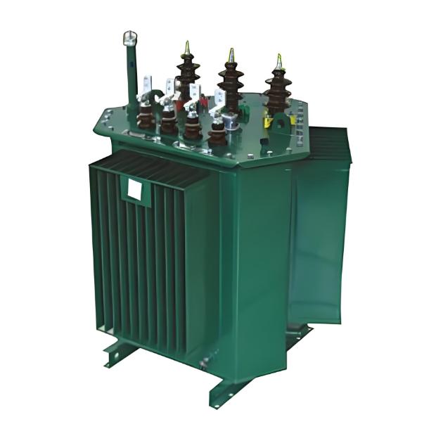
9. Bushing Installation Requirements
Bushing installation shall comply with the following requirements:
- Bushing surfaces shall be free from cracks and damage, with clean inner and outer walls.
- Bushings shall pass required tests.
- The top sealing structure shall be correctly installed with good sealing; when connecting lead wires, the top structure shall not be loosened.
10. Gas Relay and Pressure Relief Device Installation
Gas relay installation shall comply with the following requirements:
- The gas relay shall pass inspection before installation.
- The gas relay shall be installed horizontally with the marked arrow pointing toward the conservator tank; connections to the communicating pipe shall be well sealed.
- The inner wall of the pressure relief device shall be clean; the diaphragm shall be intact with materials and specifications conforming to product requirements, not to be arbitrarily substituted. When using a pressure release device, its installation direction shall comply with the product's technical specifications.
11. Conservator Tank Installation Requirements
Conservator tank installation shall comply with the following requirements:
- The conservator tank shall be cleaned before installation.
- For capsule-type conservator tanks, the capsule shall be intact without damage and shall show no air leakage during pressure testing.
- The capsule shall remain parallel to the long axis of the conservator tank without twisting; the capsule opening shall be well sealed with unobstructed breathing.
- Oil level indicators must correspond to the actual oil level in the conservator tank; oil level indicators shall move flexibly with correct signal contact positions and good insulation.
- The seal between the breather and the conservator tank connection pipe shall be good; the desiccant shall be dry; the oil seal level shall be at the oil line mark.
- The interior of the oil purifier shall be wiped clean; the desiccant shall be dry; the filter screen installation direction shall be correct and located on the outlet side.
12. Temperature Gauge and Oil Filling Procedures
Temperature gauge installation shall comply with the following requirements:
- Temperature gauges shall be calibrated before installation; signal contacts shall operate correctly with good conduction.
- The temperature gauge socket on the top cover shall be filled with transformer oil with good sealing.
- For expansion-type signal thermometers, the bending radius of the fine metal capillary tube shall not be less than 50mm and shall have no flattening or sharp twists.
- Insulating oil must pass tests according to the current national standard "Standard for Acceptance Test of Electrical Equipment in Electrical Installation Projects" before being injected into transformers. Before mixing insulating oils of different grades or mixing new oil with used oil of the same grade, oil compatibility tests must be performed.
- When filling transformers with oil, oil should preferably enter through the lower oil valve. When adding supplementary oil, it should be injected through the dedicated filling valve on the conservator tank via an oil purifier. For transformers with capsule-type conservator tanks, air must be prevented from entering during oil filling and venting to avoid false oil level readings.
- After oil filling is completed, the transformer shall remain static for 24 hours, then air shall be released multiple times from all relevant parts of the transformer until all residual gas is exhausted.
- After transformer installation is completed, an overall sealing test shall be performed with a pressure of 0.03 MPa on the tank cover for 24 hours with no leakage. Transformers transported as complete units may omit the overall sealing test.