• Product
  • Suppliers
  • Manufacturers
  • Solutions
  • Free tools
  • Knowledges
  • Experts
  • Communities
Search


How Silicon Steel Minimizes Transformer Core Loss

Echo
Field: Transformer Analysis
China

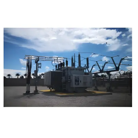
Why Transformers Use Silicon Steel Laminations to Reduce Eddy Current Loss

Transformers rely on efficient magnetic cores to transfer energy between windings with minimal loss. One of the most critical design choices is the use of laminated silicon steel sheets—not solid iron or plain steel—for the core. This decision directly addresses a major source of inefficiency: eddy current loss.

What Is Eddy Current Loss?

When a transformer operates under alternating current (AC), the primary winding generates a time-varying magnetic flux. This changing flux passes through the iron core and induces circulating currents within the core material itself. These currents—called eddy currents—flow in closed loops perpendicular to the magnetic field and dissipate energy as heat, reducing efficiency and raising operating temperatures.

Eddy current loss is one component of core (or iron) loss, the other being hysteresis loss.

Why Silicon Steel?

Silicon steel—an alloy of iron with 0.8% to 4.8% silicon—is the industry standard for power transformer cores due to two key properties:

  • High magnetic permeability: Enables strong magnetic flux density with less excitation current, allowing for more compact transformer designs.

  • Increased electrical resistivity: Silicon raises the resistivity of the steel, which inherently suppresses eddy current magnitude.

Additionally, silicon steel exhibits a narrow hysteresis loop, meaning less energy is lost during each magnetization cycle—reducing hysteresis loss and associated heating.

Transformer Core Loss.jpg

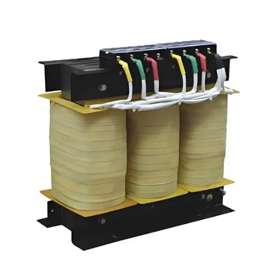
Why Laminated Sheets—Not a Solid Block?

If the core were made from a solid block of silicon steel, eddy currents would flow freely through its large cross-section, causing significant power loss and overheating.

To combat this, transformer cores are built from thin, insulated laminations—typically 0.35 mm thick cold-rolled silicon steel sheets—stacked together. This design:

  • Restricts eddy currents to narrow paths within each lamination,

  • Increases effective electrical resistance along current loops,

  • Dramatically reduces eddy current magnitude and associated heating.

The laminations are coated with an insulating oxide or varnish layer to prevent electrical contact between sheets, ensuring currents cannot bridge across layers.

Practical Design Trade-offs

In theory, thinner laminations = lower eddy current loss. However, manufacturing extremely thin sheets increases:

  • Material cost,

  • Production complexity,

  • Labor time,

  • Risk of reduced core cross-sectional area (lowering magnetic performance).

Therefore, engineers balance efficiency, cost, and manufacturability when selecting lamination thickness—0.35 mm remains the optimal standard for most distribution and power transformers.

Common core shapes include:

  • Single-phase “core-type” (single-window),

  • Three-phase “shell-type” or double-window (“日”-shaped) configurations.

Give a tip and encourage the author!

Recommended

What’s the Difference Between Rectifier Transformers and Power Transformers?
What is a Rectifier Transformer?"Power conversion" is a general term encompassing rectification, inversion, and frequency conversion, with rectification being the most widely used among them. Rectifier equipment converts input AC power into DC output through rectification and filtering. A rectifier transformer serves as the power supply transformer for such rectifier equipment. In industrial applications, most DC power supplies are obtained by combining a rectifier transformer with rectifier equ
01/29/2026
How to Judge, Detect and Troubleshoot Transformer Core Faults
1. Hazards, Causes, and Types of Multi-Point Grounding Faults in Transformer Cores1.1 Hazards of Multi-Point Grounding Faults in the CoreUnder normal operation, a transformer core must be grounded at only one point. During operation, alternating magnetic fields surround the windings. Due to electromagnetic induction, parasitic capacitances exist between the high-voltage and low-voltage windings, between the low-voltage winding and the core, and between the core and the tank. The energized windin
01/27/2026
Analysis of Four Major Power Transformer Burnout Cases
Case OneOn August 1, 2016, a 50kVA distribution transformer at a power supply station suddenly sprayed oil during operation, followed by burning and destruction of the high-voltage fuse. Insulation testing revealed zero megohms from the low-voltage side to ground. Core inspection determined that damage to the low-voltage winding insulation had caused a short circuit. Analysis identified several primary causes for this transformer failure:Overloading: Load management has historically been a weak
12/23/2025
Power Transformer Condition Monitoring: Reducing Outages & Maintenance Costs
1. Definition of Condition-Based MaintenanceCondition-based maintenance refers to a maintenance approach where repair decisions are determined by the real-time operational status and health condition of equipment. There are no fixed schedules or predetermined maintenance dates. The prerequisite for condition-based maintenance is the establishment of equipment parameter monitoring systems and comprehensive analysis of various operational information, enabling reasonable maintenance decisions base
12/22/2025
Related Products
Send inquiry
+86
Click to upload file
Download
Get the IEE Business Application
Use the IEE-Business app to find equipment, obtain solutions, connect with experts, and participate in industry collaboration anytime, anywhere—fully supporting the development of your power projects and business.