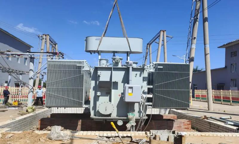
Hydraulic Leak & SF6 Gas Leakage in Circuit Breakers

Leakage in Hydraulic Operating Mechanisms
For hydraulic mechanisms, leakage can cause short-term frequent pump starting or excessively long re-pressurization time. Severe internal oil seepage in valves may lead to pressure loss failure. If hydraulic oil enters the nitrogen side of the accumulator cylinder, it can cause abnormal pressure rise, which affects the safe operation of SF6 circuit breakers.
Apart from failures caused by damaged or abnormal pressure detection devices and pressure components resulting in abnormal oil pressure, and faults such as failure to close or open due to tripping/closing solenoid coils, first-stage valve push rods, or auxiliary switch signal issues, almost all other faults in hydraulic mechanisms are caused by leakage—including nitrogen leakage.
Main oil leakage locations in hydraulic mechanisms include: three-way valves and drain valves, high/low-pressure oil pipes, joints of pressure gauges and pressure relays, damaged seals at piston rods of working cylinders and accumulator cylinders, and sand holes in low-pressure oil tanks.
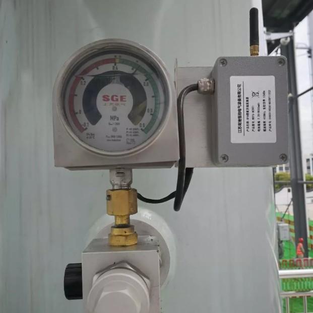
(1) Leakage at pipe joints of high/low-pressure oil lines, pressure gauges, and pressure relays
Pipe joint leakage accounts for a relatively large proportion among all hydraulic mechanism leaks, approximately 30%. Hydraulic oil pipes and joints achieve sealing via "ferrules". If the machining accuracy, tightening strength is improper, or burrs exist at the connection, oil leakage may occur. During handling, slightly tighten the joint first; if leakage persists, remove the oil pipe and reassemble it correctly. The tightening torque during assembly should not be too high or too low to avoid damaging the ferrule—tighten only until no oil seepage occurs.
(2) Oil leakage due to poor seals
Hydraulic mechanisms generally use two types of sealing: rigid sealing and elastic sealing. Elastic sealing includes:
"O"-ring rubber seals, which utilize elastic deformation for static or dynamic sealing on flat or circular surfaces.
"V"-type seals, which are directional—the open side of the "V" must face the high-pressure side.
Poor quality or improper installation of sealing rings, burrs on piston rods, contaminants in the oil, or wear during movement can cause seal failure. Insufficient compression, aging, or damage also lead to leakage. When such conditions are found, the seals should be replaced.

(3) Valve body seal leakage
Sealing at the mating surfaces of valves such as three-way valves and drain valves mostly uses rigid sealing, typically achieved through valve line sealing. For example, ball valves rely on tight contact between a steel ball and the valve seat for sealing, while conical valves depend on tight fit between the conical surface and the valve port.
Main causes of leakage at valve mating surfaces include: poor sealing fit accuracy, excessive surface roughness and flatness errors, poor machining precision, presence of impurities at the mating surface during assembly or operation, leading to damage of the sealing surface.
Handling methods:
Remove burrs from relevant components;
If the hydraulic oil is dirty or substandard, replace or filter it;
For faulty ball valve seals, reassemble carefully—the sealing surface should not be too wide, and a new, high-precision steel ball must be used;
For poor conical seals, carefully lap and repair;
If seal wear is severe and irreparable, replace the entire component.
(4) Housing leakage
Housing leakage usually results from defects in castings or welds that expand under pressure shock from the hydraulic system. For example, if there is seepage at the welds of oil tanks or nitrogen cylinders (accumulators), welding repair is required.
(5) SF6 Gas Replenishment
Before charging SF6 circuit breakers, qualified SF6 gas should be used to purge the charging pipeline for 5 seconds to remove air inside the pipeline. During operation, ensure cleanliness of the charging interface. In high humidity conditions, an electric hot air blower may be used to dry the interface. Ideally, adjust the charging pressure to be nearly equal to the internal SF6 pressure in the circuit breaker before connecting the charging hose. The pressure difference should generally be less than 100 kPa. Direct high-pressure charging without a pressure reducer is prohibited. The pressure of the gas charged into the circuit breaker should be slightly higher than the specified value to compensate for gas consumed during future moisture measurements.
(6) SF6 Gas Moisture Detection
The moisture content in SF6 gas significantly affects the arc-quenching performance, insulation strength, and service life of electrical equipment. When moisture exceeds limits, toxic or corrosive compounds may form under high temperatures during arcing, corroding metal components inside the arc chamber and potentially causing circuit breaker explosion.
Therefore, moisture measurement should be conducted 24 hours after SF6 gas is filled into the equipment. Before measurement, check that the internal SF6 gas pressure is slightly above rated pressure. Measurements should be taken during dry weather with low ambient humidity, using dedicated pipelines, typically no longer than 5 meters. The measurement pipeline must be flushed with dry nitrogen or qualified new SF6 gas before measurement.
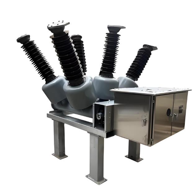
(7) SF6 Gas Leak Detection
Common leak locations on SF6 circuit breakers include: drive rods and scratched seals in support insulators, poor sealing at charging valves, cracks at the base of porcelain supports, flange connections, sand holes at the interrupter cover, triple-box cover plates, gas piping joints, density relay interfaces, secondary pressure gauge joints, welds, and mismatch between sealing grooves and seals (gaskets).
Before testing, blow away any surrounding SF6 gas. Then slowly move the leak detector probe 1–2 mm above the test point. Under normal conditions, the detector needle remains stable. If the needle fluctuates and residual gas is suspected, blow air to disperse it for 1 hour and then continue measuring.