
As the global energy crisis worsens and environmental pollution grows more severe, governments worldwide are boosting support for R&D in new energy power generation. The household use of solar distributed generation, a key next - phase direction for the PV industry, has gained increasing attention. However, issues like power output fluctuations of PV components and the rationality of energy storage unit integration can seriously affect household electricity use. Thus, to coordinate stable energy flow between system units and ensure smooth operation, an energy management strategy is needed to balance supply and demand. This paper, based on household PV - energy storage systems, studies energy management to enable stable operation and provide a theoretical basis for practical clean energy applications.
1 Analysis of System Structure and Energy Management Algorithm
The topology of the studied household PV - energy storage system (Figure 1) comprises PV modules, lithium - ion storage batteries, power converters, the grid, and user loads. PV module output forms a common DC bus voltage via a Boost converter. Lithium - ion batteries connect to this bus through a Buck - Boost converter. The DC bus then feeds power into the single - phase grid or supplies loads independently via a full - bridge inverter.
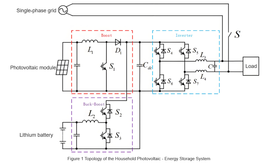
The system prioritizes "self-generation and self-consumption". PV module output, as the primary power source, first meets user loads. Surplus/deficit PV power is balanced by lithium batteries (secondary source); if both PV and batteries hit limits, the grid (tertiary source) ensures stable supply.
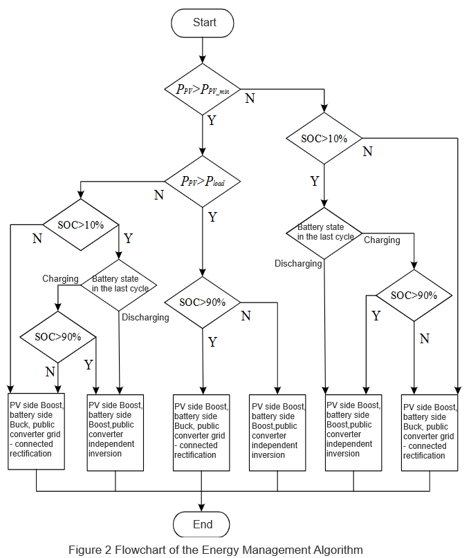
For PV output, battery SOC, and charge-discharge power: If PPV < PPV-min}\), the Boost converter shuts down (no power output); otherwise, it operates. Batteries stop charging when SOC > 90% and discharging when SOC < 10%. Pbat adjusts dynamically with PPV and Pload, ranging from 0 to max battery charging power. To avoid frequent charge-discharge oscillations, the next cycle's state depends on the previous cycle's battery status, preventing frequent system mode switches.
Based on this, an energy management algorithm for household PV-storage systems is proposed, as shown in Figure 2.
2 Analysis of System Operation Modes and Energy Flow
Guided by the energy management algorithm, the system’s operation splits into independent and grid - connected modes, each further subdivided as follows:
2.1 Independent Operation (By Main Power)
Two sub - modes exist, defined by the power source controlling the DC bus:
2. 2 Grid - Connected Operation (By Inverter State)
Split by whether the inverter is in inversion or rectification:
2.3 Mode Boundaries & Coordination
The 4 sub - modes’ trigger conditions and equipment coordination are detailed in Table 1 (to be added). Through dynamic switching of “PV - battery - grid” power and adaptive control of Boost/Buck - Boost converters and the inverter, the system enables efficient energy flow in “generation - storage - consumption”, covering all household power needs (off - grid, grid - connected, emergency, etc.).
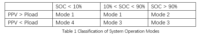
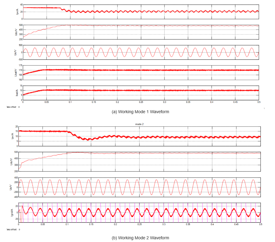
Figure 3(a) shows the waveform for Mode 1: PV output = 4.8 kW, load = 3 kW. The PV module outputs 240 Vdc; the Boost converter stabilizes the DC bus at 480 Vdc. The inverter runs in independent inversion (220 Vac for loads), and the Buck - Boost works in Buck mode (1.8 kW to charge the battery). Waveforms (top to bottom): PV output current, DC bus voltage, inverter output voltage, and battery charging current.
Figure 3(b) corresponds to Mode 2: PV output = 5 kW (battery full, so Buck - Boost is off). Load = 3 kW; the inverter uses grid - connected inversion to keep the DC bus at 480 Vdc, feeding excess energy to the grid (9 A, synchronized with grid voltage). Waveforms: PV output current, DC bus voltage, inverter output voltage, and grid - connected current.
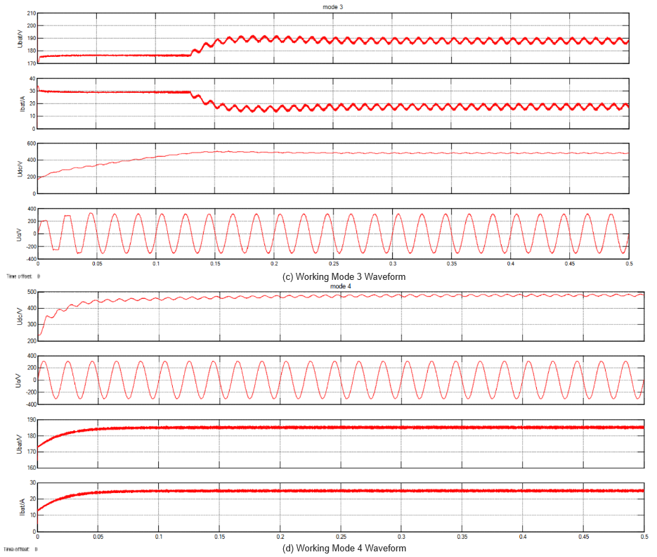
Figure 3(c) shows Mode 3: The PV module hits limits (no output, Boost off). The energy storage unit powers the system; the Buck - Boost runs in Boost mode (DC bus = 480 Vdc). The inverter uses independent inversion (220 Vac for 3 - kW loads). Waveforms: Battery discharge current, DC bus voltage, and inverter output voltage.Figure 3(d) presents Mode 4: Both PV and energy storage hit limits (no output). The grid powers loads (3 kW) and charges the battery; the inverter uses grid - connected rectification (DC bus = 480 Vdc).
3. Conclusion (Street - lamp Maintenance)
Current urban street - lamp maintenance has shortcomings. To improve, focus on four areas:
These steps will enhance street - lamp management efficiency, supporting smart city operations and green development.


