• Product
  • Suppliers
  • Manufacturers
  • Solutions
  • Free tools
  • Knowledges
  • Experts
  • Communities
Search


What is the operation mode of the step-up transformer in photovoltaic power generation?

Echo
Field: Transformer Analysis
China

1 Overview of Photovoltaic Power Generation Process

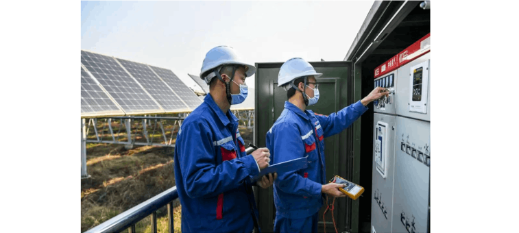
In my daily work as a frontline operation and maintenance technician, the photovoltaic power generation process I encounter involves connecting individual solar panels into photovoltaic modules, which are then paralleled through combiner boxes to form a photovoltaic array. Solar energy is converted into direct current (DC) by the photovoltaic array, then transformed into three-phase alternating current (AC) via a three-phase inverter (DC-AC). Subsequently, a step-up transformer increases the voltage to match the requirements of the public power grid, enabling the integration and distribution of electrical energy to grid-connected equipment.

2 Classification of Common Faults in Photovoltaic Power Generation Operation
2.1 Substation Operation Faults

During maintenance, substation faults can be categorized into transmission line faults, busbar faults, transformer faults, high-voltage switch and auxiliary equipment faults, and relay protection device faults. These directly impact the voltage transformation and transmission of electrical energy.

2.2 PV Area Operation Faults

Faults in the PV area often stem from substandard installation practices, such as issues with solar panels, strings, and combiner boxes due to improper installation, inverter malfunctions from inadequate commissioning, and faults in step - up transformer auxiliary equipment. Additionally, oversight during inspections can lead to undetected potential hazards, exacerbating potential failures.

2.3 Communication and Automation Faults

While communication and automation system faults may not immediately affect power generation, they hinder operational analysis, defect detection, and remote control capabilities, posing safety risks that could escalate if unaddressed.

2.4 Geographical and Environmental Faults

Environmental factors can cause equipment deformation due to soil settlement, electrical short circuits from insufficient safety clearances, corrosion from salt spray, insulation degradation from moisture, and short circuits caused by wildlife intrusion.

3 Root Causes of Common Faults

Theoretically, accidents and major faults can be prevented through strict management. However, in practice, electrical safety incidents and equipment failures persist due to:

  • Design flaws in early PV projects resulting from rushed development and lack of experience.

  • Compromised construction quality due to tight schedules, leading to substandard workmanship and long-term operational risks.

  • Inability to assess equipment reliability without comprehensive operational testing, resulting in the use of low-quality components.

  • Skill gaps among maintenance personnel, with many being new hires reliant on outdated training methods, lacking proficiency in fault diagnosis and emergency response.

4 Solutions

Technical strategies to address common faults in PV power stations include:

  • Rigorous upfront planning to ensure designs align with site-specific conditions.

  • Comprehensive infrastructure management with strict contractor vetting and quality control.

  • Stringent equipment qualification to exclude substandard products.

  • Enhanced training programs to improve personnel responsibility and technical expertise.
    Implementation of these measures can significantly reduce fault occurrence.

4.1 Substation Fault Handling

Substation faults follow standard electrical fault management protocols. In the event of busbar outages or line trips, single - busbar substations may experience complete station blackout, triggering islanding protection and inverter shutdown. Operators must:

  • Secure auxiliary power and verify backup systems for DC and communication.

  • Analyze protection device actions to identify fault types.

  • Inspect primary systems, locate faults, and coordinate with grid operators for safe restoration.

4.2 PV Area Fault Causes

Key factors contributing to PV area faults include:

  • Poor installation practices, such as loose connections, substandard components, and inadequate sealing in combiner boxes.

  • Ineffective coordination among installation, wiring, and commissioning teams for inverters and transformers.

  • Environmental degradation, particularly corrosion from coastal salt spray and insulation breakdown.

  • Wear and tear from prolonged operation, including loosening of fan components, terminal blocks, and enclosure latches.

4.3 Fault Prevention Strategies

Preventive measures for electrical equipment faults involve:

  • Ensuring construction quality meets operational standards before handover.

  • Proactive technical supervision and environmental risk mitigation during operation.

  • Cultivating personnel accountability and analytical skills through targeted training.

4.4 Fault Detection and Handling

Hidden faults between solar panels and combiner boxes, which cause energy loss without obvious symptoms, can be detected using clamp meters to measure string currents. Faulty components, fuses, or connections should be promptly replaced.

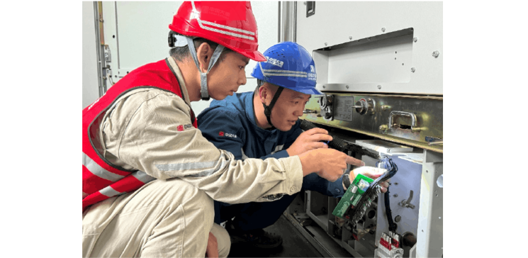
4.4.1 Combiner Box Faults

Common issues include seal failures, communication module malfunctions, and overheating from loose terminals. Regular inspections during spring maintenance, including resealing and tightening connections, can mitigate summer overheating risks.

4.4.2 Inverter Faults

Inverter failures, often manifesting as shutdowns or startup issues, are prevalent during initial operation. Post-commissioning, overheating due to poor ventilation or component/software malfunctions is typical. Preventive measures include regular filter cleaning and fan inspections.

4.4.3 Step-Up Transformer Faults

Modern dry-type transformers rarely fail, but common issues include ingress of wildlife due to poor sealing, fan malfunctions, and valve latch failures. In coastal or hybrid projects, cable terminations and surge arresters require extra vigilance to prevent collector line outages. Fault prevention relies on routine inspections and technical monitoring.

Give a tip and encourage the author!
Recommended
Why Do Contactors Always Burn Out? Overload and Short-Circuit Protection Must Be Implemented Simultaneously
Contactors are used to close and open loads that require such operations during normal use, particularly for specific activities like medium-voltage public lighting and industrial electric motors.The medium-voltage contactor + fuse combination controller (F-C) can control motors up to 12 kV. However, medium-voltage controllers are also suitable as feeders for other types of loads, especially transformers. For such loads, contactors are usually modified to include mechanical latching, so that the
Echo
09/11/2025
High-Voltage DC Contactor Wiring Essentials: Polarity Requirements and Safety Guidelines
High-Voltage DC Contactors Usually Have Polarity DistinctionsThis is especially true in application scenarios with high current and high voltage.Why Polarity Distinctions ExistArc CharacteristicsDC current has no zero-crossing point, making arc extinction more difficult than that of AC. Polarity (current direction) may affect the stretching and extinguishing effect of the arc.Internal Structural DesignSome contactors optimize arc-extinguishing devices (such as magnetic blowout coils and permanen
Echo
09/09/2025
Working Principle of Low-Voltage Vacuum Contactors and Their Application in DF100A Shortwave Transmitters
In power systems, low-voltage vacuum contactors are used for remotely connecting and disconnecting circuits, as well as frequently starting and controlling AC motors. They can also form electromagnetic starters together with various protection devices.Due to their longer service life, higher reliability, and auxiliary switches compatible with electronic equipment, low-voltage vacuum contactors can fully replace traditional air AC contactors. They are applied in important scenarios across sectors
Echo
09/09/2025
A hybrid DC circuit breaker
Most DC molded-case circuit breakers use natural air arc extinction, and there are typically two arc extinguishing methods: one is conventional opening and closing, where the contacts axially stretch the arc, while the conductive circuit generates a magnetic field that bends and elongates the arc, pulling it lengthwise perpendicular to the arc axis. This not only increases the arc length but also induces lateral motion, enabling air cooling to achieve arc extinction.The other method involves the
Echo
09/02/2025
Seed Inquiry
Download
Get the IEE Business Application
Use the IEE-Business app to find equipment, obtain solutions, connect with experts, and participate in industry collaboration anytime, anywhere—fully supporting the development of your power projects and business.