
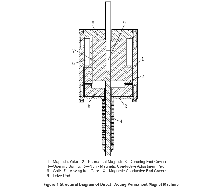
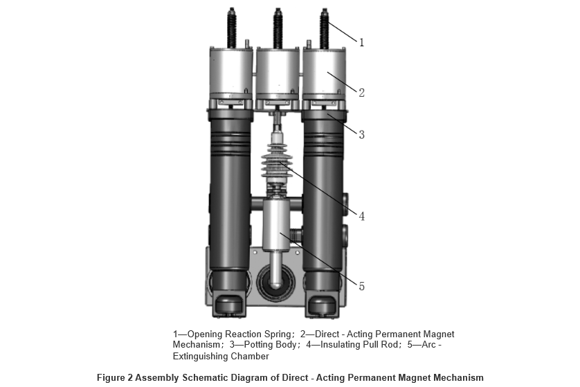
Due to the high demand for miniaturization in solid-insulated ring main units (RMUs), traditional single permanent magnet mechanisms with three-phase interlocking cannot meet the overall miniaturization requirements of the equipment. Therefore, the permanent magnet mechanism designed in this context adopts a three-phase independent direct-acting structure. Each phase's arc extinguishing chamber unit is integrally cast with the casting body of the RMU and connected to the permanent magnet mechanism via an insulating rod in a linear configuration. The opening counterforce spring is positioned on the drive shaft of each phase’s permanent magnet mechanism. The overall structure of a single direct-acting permanent magnet mechanism is shown in Figure 1, and its assembly schematic diagram within the solid-insulated RMU is illustrated in Figure 2.
2.Mathematical Model of the Permanent Magnet Mechanism Drive Circuit
The direct-acting permanent magnet mechanism designed herein is based on the principle of a single-stable state permanent magnet mechanism. It employs a drive method where an energized capacitor discharges to actuate the permanent magnet mechanism. The circuit diagram is shown in Figure 3, where C represents the capacitor used for driving the permanent magnet mechanism, R denotes the equivalent resistance of the permanent magnet mechanism's coil, and L indicates the equivalent inductance of the coil.

The dynamic characteristics of the single-stable permanent magnet mechanism satisfy the system of differential equations shown in Equation (1):

where i is the opening or closing current through the coil (A); uC is the initial voltage of the charging capacitor (V); R is the equivalent resistance of the coil (Ω); C is the capacitance of the charging capacitor (F); ψ is the total magnetic flux linkage of the electromagnetic system (Wb); m is the equivalent mass of the moving parts referred to the moving core (kg); x is the displacement of the moving core (m); v is the velocity of the moving core (m/s); Fx is the electromagnetic force acting on the moving core (N); Ff is the counteracting force on the moving core (N). Solving this system of equations yields the dynamic characteristics of the permanent magnet mechanism.

3.Counterforce Equivalence
The main counterforces in the ring main unit's circuit breaker include the contact pressure of the arc extinguishing chamber and the opening spring force of the permanent magnet mechanism. These counterforces are equivalently referred to the moving core of the permanent magnet mechanism. The arcing chamber has a contact opening distance of 9.5 mm and an over-travel of 2.5 mm, with a total mechanism stroke of 12 mm. The counterforces of the opening spring and contact spring are measured according to the motion stroke of the permanent magnet mechanism, and the counterforce curve is plotted based on specific data. The detailed counterforce equivalence points are shown in Table 1.

4 Simulation Model Establishment
The dynamic characteristics of the direct-acting permanent magnet mechanism are solved using the finite element method (FEM). The basic principle of FEM is to discretize the continuous solution domain into a finite number of elements interconnected at nodes. After individual element analysis, a global assembly is performed, and boundary conditions are applied, with the final solution obtained via computer computation. In this study, the Ansoft finite element simulation software is used to establish the simulation model of the permanent magnet mechanism, and material parameters of its components are set. The permanent magnet material is defined as NdFe35, and the yoke material as steel-1010.
Next, the coil parameters are assigned: charging voltage of the capacitor is 110 V, capacitance is 0.047 F, coil DC resistance is 5 Ω, number of turns is 500, and inductance is 0.0143 H. Since the direct-acting permanent magnet mechanism is of a single-stable type, the opening operation is driven by the opening spring force. Therefore, only a small reverse current is needed to generate a reverse magnetic flux to cancel the flux produced by the permanent magnet, enabling the mechanism to open under the spring's counterforce. To reduce the required reverse magnetic flux, after extensive simulation and testing, a 5 Ω DC resistor is added in series in the opening drive circuit.
Finally, surface and solid modeling and meshing are performed on the permanent magnet mechanism. A relatively dense mesh is applied to key magnetic components such as the moving core, magnetic end caps, yoke, and permanent magnet, while a coarser mesh is used for non-magnetic parts.
5 Analysis of Simulation and Experimental Results
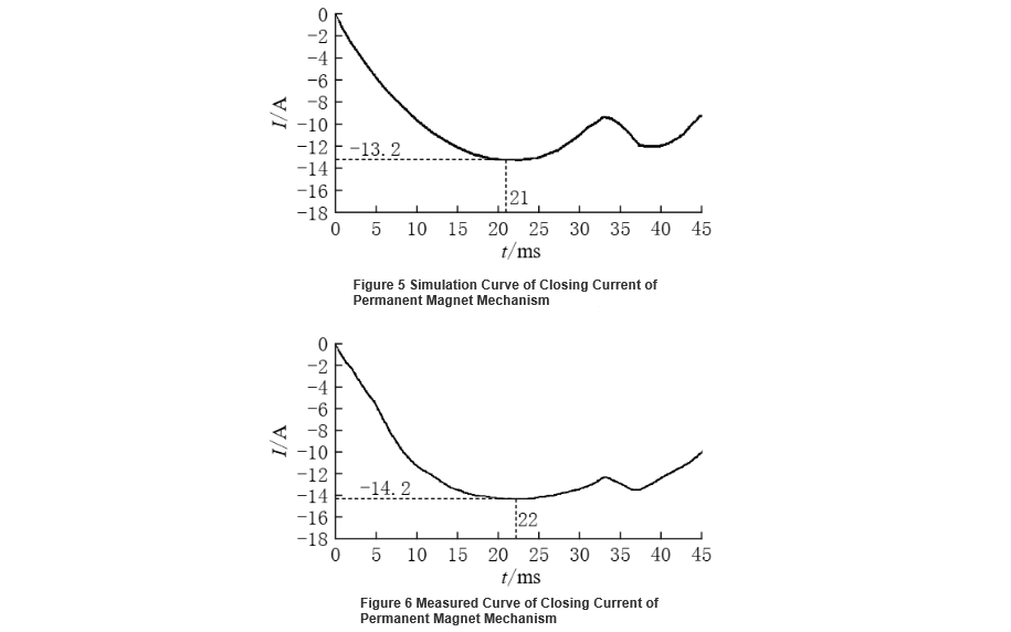
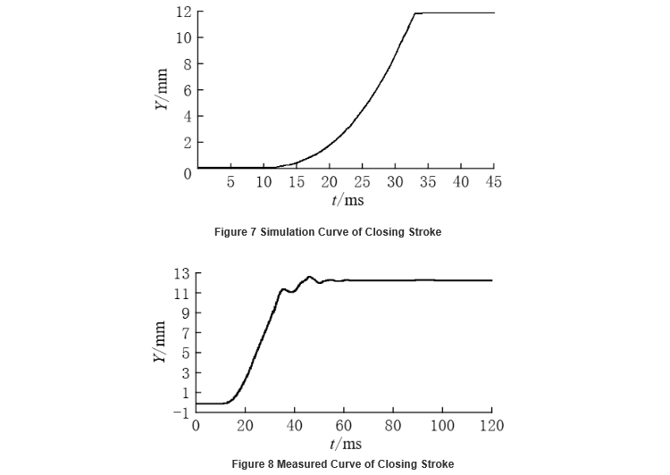
The electrical and mechanical characteristics of the direct-acting permanent magnet mechanism are analyzed by combining Ansoft simulations with actual product tests, focusing on the closing and opening current and stroke characteristics. Figure 5 shows the simulated closing current curve, with a peak current of 13.2 A. Figure 6 shows the oscilloscope-measured closing current, with a measured peak of 14.2 A. Figure 7 presents the simulated closing stroke curve, yielding a closing speed (average speed over the last 6 mm before contact closure) of 0.8 m/s. Figure 8 shows the oscilloscope-measured closing speed, which is 0.75 m/s. The results indicate that the closing mechanical characteristics of the designed direct-acting permanent magnet mechanism for the solid-insulated ring main unit meet the requirements of switchgear, and the error between simulation and experimental results falls within the acceptable design range.
6 Conclusion
This paper designed a direct-acting permanent magnet mechanism for solid-insulated ring main units. The closing and opening currents and mechanical stroke characteristics of the mechanism were analyzed and compared using computer simulation and actual product testing. The results show that the established dynamic characteristic simulation model can serve as a theoretical basis for practical permanent magnet mechanism design. The direct-acting permanent magnet mechanism is well-suited for use in solid-insulated ring main units, featuring low drive current and excellent mechanical performance such as closing and opening speeds, fully meeting technical requirements. It also provides a technical foundation for the future development of high-voltage synchronous phase selection switches.


