• Product
  • Suppliers
  • Manufacturers
  • Solutions
  • Free tools
  • Knowledges
  • Experts
  • Communities
Search


Six Troubleshooting Tips for Stepper Servo Motor Issues

Felix Spark
Felix Spark
Field: Failure and maintenance
China

Stepper servo motors, as critical components in industrial automation, directly impact equipment performance through their stability and precision. However, in practical applications, motors may exhibit abnormalities due to parameter configuration, mechanical load, or environmental factors. This article provides systematic solutions for six typical issues, combined with real-world engineering cases, to help technicians quickly identify and resolve problems.

1. Abnormal Motor Vibration and Noise

Vibration and noise are the most common failure symptoms in stepper servo systems. A packaging production line once experienced sharp whistling during motor operation. Testing revealed that the resonance frequency coincided with the natural frequency of the mechanical structure. Solutions include: first, adjusting stiffness parameters (e.g., PA15, PB06) via the servo drive and enabling adaptive filter functions to suppress vibrations at specific frequencies; second, checking coupling alignment accuracy—parallelism deviation must be controlled within 0.02 mm; if belt transmission is used, verify uniform tension. Notably, when operating at low speeds (e.g., below 300 rpm), enabling Hybrid Decay mode can suppress mid-frequency vibration. For high-frequency noise, install ferrite core filters at the motor power input. One medical device manufacturer reduced noise by 12 dB using this method.

2. Positioning Accuracy Drift

A CNC machine exhibited cumulative error of 0.1 mm/hour during continuous machining, traced to encoder signal interference. Resolution steps include: (1) using a differential probe to check signal integrity of encoder cables (A+/A-, B+/B-); replace with shielded twisted-pair cables if waveform distortion exceeds 15%; (2) verifying that the servo drive’s electronic gear ratio (numerator PA12 / denominator PA13) matches the mechanical reduction ratio—one automated production line had an erroneous denominator setting of 32767, causing 0.03° error per revolution; (3) for absolute encoder systems, perform periodic homing calibration, preferably using a dual-frequency laser interferometer for compensation. In practice, installing signal isolation amplifiers enhances noise immunity—one semiconductor equipment manufacturer achieved ±1 μm repeatability after implementation.

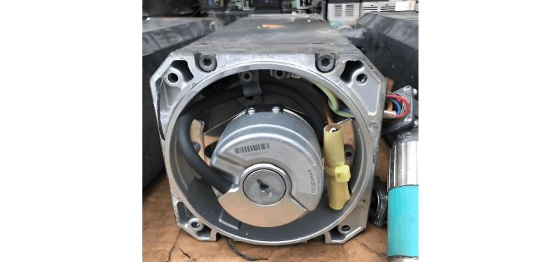
Stepper Servo Motor.jpg

3. Motor Overheating Protection Trigger

When motor surface temperature consistently exceeds 80°C, thermal protection forces shutdown. An injection molding robot frequently reported Err21.0 overheating faults. Analysis showed: (1) excessive current loop settings (PA11)—with actual load current at only 60% of rated value, reducing current limit by 20% resolved the issue; (2) inadequate motor cooling—adding forced-air cooling lowered temperature by 15–20°C; (3) for frequent start-stop operations, select motors with better inertia matching. In one case, increasing pulse resolution from 1600 ppr to 6400 ppr reduced iron losses by 37%. Note: for every 10°C rise in ambient temperature, motor rated torque must be derated by 8%.

4. Sudden Step Loss

At high speeds (e.g., above 1500 rpm), stepper motors are prone to step loss due to insufficient torque. A chip mounter showed position lag during acceleration. Solutions include: (1) optimizing S-curve acceleration/deceleration profiles—set jerk (jerk parameter) to 30–50% of acceleration value; (2) monitoring power supply voltage fluctuations—the minimum operating voltage for a 24V system should not drop below 21.6V; (3) for high-inertia loads, enable feedforward compensation (parameter PF03) in the servo drive. A textile machinery manufacturer reduced high-speed step loss rate from 0.3% to below 0.01% by adding flywheel inertia compensation. Critical note: when load-to-motor inertia ratio (JL/JM) exceeds 30:1, motor reselection is mandatory.

5.Communication Interruption Troubleshooting

Bus-controlled systems (e.g., EtherCAT, CANopen) are susceptible to communication timeouts. A lithium battery production line experienced servo network disconnections every two hours, ultimately traced to: (1) missing termination resistors causing signal reflection—adding 120Ω resistors at end nodes reduced bit error rate by 90%; (2) suboptimal network topology—replacing daisy-chain with star topology improved reliability; one case showed fiber-optic repeaters reduced communication latency from 200 μs to 50 μs; (3) outdated servo drive firmware—a known CRC checksum defect was fixed in the latest version. Important: for PROFINET networks, ensure each node’s device name is correctly bound to its IP address.

6. Brake Malfunction Handling

For servo motors with electromagnetic brakes, a warehouse stacker crane once experienced post-power-off slippage. Corrective actions included: (1) verifying brake response time—24V brakes must actuate within <50 ms; (2) regularly measuring brake pad wear—replace when remaining thickness <1.5 mm; (3) adding pre-braking logic in the PLC program to trigger the brake signal 50 ms early. A port AGV system added supercapacitor backup power to ensure reliable brake engagement during outages. For vertical-axis applications, recommend additional mechanical stops as secondary protection.

Advanced Optimization Recommendations

Beyond the above solutions, establish a preventive maintenance system: 

  • Monthly record three-phase current imbalance (alert if deviation >10%); 

  • Quarterly insulation resistance testing of windings with a megohmmeter (≥100 MΩ); 

  • Utilize the servo drive’s built-in fault waveform capture for anomaly analysis. One automotive welding line found that when current total harmonic distortion (THD) exceeded 8%, motor failure probability increased fivefold—proactive replacement of filter capacitors improved MTBF by 40%.

Through systematic fault analysis and solution implementation, overall efficiency of stepper servo systems can improve by over 25%. Engineers are advised to maintain complete parameter backup archives to rapidly restore optimal configurations during equipment relocation or component replacement. With the advancement of predictive maintenance technologies, future integration of vibration sensors and current waveform analysis will enable more precise fault prediction.

Give a tip and encourage the author!
Recommended
What are the hazards of high-order harmonics to electrical equipment?
Voltage distortion in AC power systems causes unequal intervals between the firing pulses of the control angle in conventional converters, and through positive feedback, it amplifies the system voltage distortion, resulting in unstable rectifier operation. In inverters, continuous commutation failures may occur, preventing normal operation and even damaging commutation equipment.For star-connected transformers, third-order and triplen harmonics can cause third-harmonic oscillation when the windi
Felix Spark
11/06/2025
How to Identify Internal Faults in a Transformer?
Measure DC resistance: Use a bridge to measure the DC resistance of each high- and low-voltage winding. Check whether the resistance values among phases are balanced and consistent with the manufacturer’s original data. If phase resistance cannot be measured directly, line resistance may be measured instead. The DC resistance values can indicate whether the windings are intact, whether there are short circuits or open circuits, and whether the contact resistance of the tap changer is normal. If
Felix Spark
11/04/2025
What Are the Common Inverter Fault Symptoms and Inspection Methods? A Complete Guide
Common inverter faults mainly include overcurrent, short circuit, ground fault, overvoltage, undervoltage, phase loss, overheating, overload, CPU malfunction, and communication errors. Modern inverters are equipped with comprehensive self-diagnostic, protection, and alarm functions. When any of these faults occurs, the inverter will immediately trigger an alarm or shut down automatically for protection, displaying a fault code or fault type. In most cases, the fault cause can be quickly identifi
Felix Spark
11/04/2025
Handling 35kV Substation Fault Tripping
Analysis and Handling of Fault Tripping in 35kV Substation Operation1. Analysis of Tripping Faults1.1 Line-Related Tripping FaultsIn power systems, the coverage area is extensive. To meet power supply demands, numerous transmission lines must be installed—posing significant management challenges. Especially for special-purpose lines, installations are often located in remote areas such as suburbs to minimize impact on residential life. However, these remote areas have complex environments, makin
Leon
10/31/2025
Related Products
Send inquiry
Download
Get the IEE Business Application
Use the IEE-Business app to find equipment, obtain solutions, connect with experts, and participate in industry collaboration anytime, anywhere—fully supporting the development of your power projects and business.