0 Introduction
Dissolved gas analysis (DGA) in insulating oil is a crucial test for large oil-immersed power transformers. By employing gas chromatography, it is possible to timely detect the aging or changes in internal insulation oil of oil-filled electrical equipment, identify potential faults such as overheating or electrical discharges at an early stage, and accurately assess the severity, type, and development trend of the fault. Gas chromatography has become an essential method for monitoring and ensuring the safe and stable operation of equipment, and it has been incorporated into relevant international and domestic standards [1,2].
1 Case Study
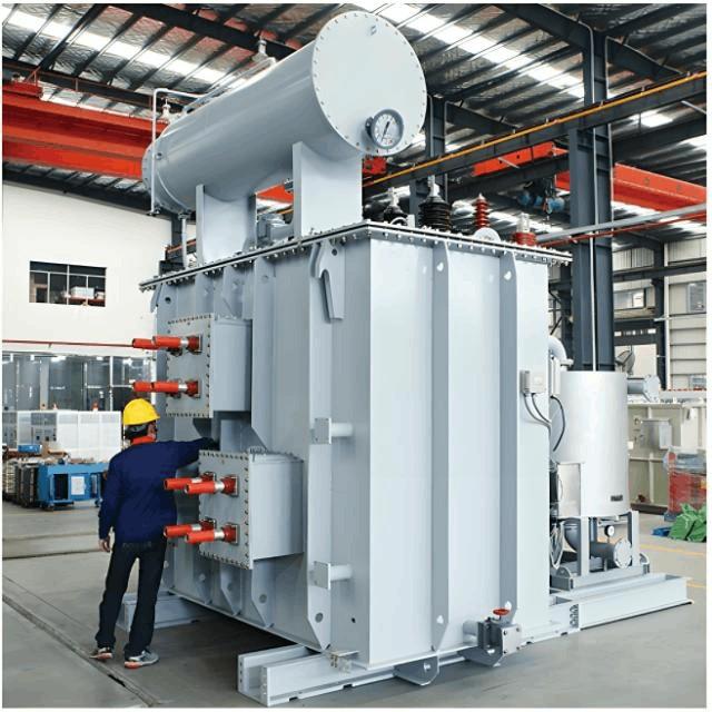
The No. 1 main transformer at Hexin Substation is model A0A/UTH-26700, with a voltage configuration of 525/√3 / 230/√3 / 35 kV. It was manufactured in May 1988 and commissioned on June 30, 1992. On September 20, 2006, the computer monitoring system indicated a "light gas relay operation on No. 1 main transformer." Subsequent inspection by operating personnel revealed cracks and severe oil leakage at both the beginning and end bushings of Phase B on the 35 kV side, along with the presence of gas in the gas relay, prompting an immediate request for shutdown. Prior to this incident, routine electrical tests and insulating oil monitoring tests had shown no abnormalities.
2 Gas Chromatography Analysis and Fault Diagnosis
Oil and gas samples were collected immediately after shutdown for chromatographic testing. The test results are shown in Tables 1 and 2. The results indicated abnormal concentrations of dissolved gases in both the transformer oil and the gas relay. Comprehensive analysis was performed using chromatographic data and the equilibrium criterion method to evaluate the gas concentrations in oil and gas samples.
Table 1 Chromatographic Record of Insulating Oil from Phase B of No. 1 Main Transformer at Hexin Substation (μL/L)
Analysis Date |
H₂ |
CH₄ |
C₂H₆ |
C₂H₄ |
C₂H₂ |
CO |
CO₂ |
C₁+C₂ |
06-09-20 |
21.88 |
12.27 |
1.58 |
10.48 |
12.13 |
33.42 |
655.12 |
36.46 |
Table 2 Chromatographic Record of Gas from Gas Relay of Phase B of No. 1 Main Transformer at Hexin Substation (μL/L)
Gas Component |
H₂ |
CH₄ |
C₂H₆ |
C₂H₄ |
C₂H₂ |
CO |
CO₂ |
C₁+C₂ |
Measured Gas Concentration |
249,706.69 |
7,633.62 |
24.93 |
2,737.51 |
6,559.62 |
9,691.52 |
750.38 |
16,955.68 |
Theoretical Oil Concentration |
14,982.40 |
2,977.11 |
57.34 |
3,996.76 |
6,690.81 |
1,162.98 |
690.35 |
13,722.03 |
qᵢ (αᵢ) |
685 |
243 |
36 |
381 |
552 |
35 |
1 |
376 |
According to the Quality Standards for Transformer Oil in Service, attention should be paid when any of the following dissolved gas concentrations in oil of 500 kV transformers exceed the specified values: total hydrocarbons: 150 μL/L; H₂: 150 μL/L; C₂H₂: 1 μL/L. Acetylene (C₂H₂) was detected in the transformer oil with a concentration φ(C₂H₂) of 12.13 μL/L, exceeding the attention threshold by more than 12 times. Based on the component exceedance analysis method [3], it was preliminarily determined that an internal fault existed in the transformer.
Further analysis based on characteristic gases indicated a high-energy discharge fault, since φ(C₂H₂) is a key indicator distinguishing overheating from electrical discharge. Using the IEC three-ratio method, the calculated ratios were:
• φ(C₂H₂)/φ(C₂H₄) = 1.2,
• φ(CH₄)/φ(H₂) = 0.56,
• φ(C₂H₄)/φ(C₂H₆) = 6.6,
resulting in a code of 102. This led to the preliminary conclusion that a high-energy discharge (i.e., arcing) had occurred within the transformer.
Using the equilibrium criterion method [4] and the gas composition in the gas relay, theoretical oil concentrations were calculated based on the different solubilities of gases in oil. The ratio αᵢ of theoretical to measured concentrations in oil was derived (see Table 2). Based on field experience, under normal conditions, αᵢ values for most components fall within the range of 0.5–2. However, during sudden faults, characteristic gases typically exhibit αᵢ values significantly greater than 2. In this case, all gas components in the gas relay showed αᵢ values much greater than 2, indicating a sudden internal fault.
Electrical test results showed that the on-load tap changer contact resistances, winding DC resistances, and maximum phase differences were all within acceptable limits. Leakage currents between windings and to ground, as well as their historical comparisons, showed no abnormalities. Dielectric loss and insulation resistance parameters were also normal. These results ruled out overall moisture ingress, major insulation degradation, or widespread insulation defects, confirming that the main insulation system was intact.
Based on comprehensive analysis of the above results, it was concluded that a sudden arcing fault had occurred inside the transformer. The concentrations of CO and CO₂ in the oil did not show significant increases, and although total hydrocarbon levels were rising, they had not yet exceeded limits. This suggested that large-scale solid insulation involvement was unlikely. However, due to the high αᵢ values for CO and total hydrocarbons, there was suspicion of a sudden discharge fault involving localized damage to solid insulation.
3 Internal Inspection and Remedial Actions
To further determine the root cause, the transformer was drained and inspected. The two 35 kV bushings and riser on Phase B were removed for examination, revealing that the voltage-equalizing grounding strip on the coil end pressure plate had been burned through. Upon lifting the tank cover, it was found that the insulating support of the upper yoke coil pressure plate had been damaged due to long-term mechanical stress, resulting in a two-point grounding. This created a circulating current, leading to arcing that burned through the grounding strip. The large volume and high rate of gas generation created significant internal pressure, causing cracks and severe oil leakage in the two 35 kV bushings near the discharge point. The inspection findings were fully consistent with the conclusions drawn from chromatographic analysis.
Remedial Measures:
• Replace the damaged insulating support components;
• Perform degassing and filtration of the insulating oil;
• Return the transformer to normal operation after successful acceptance testing;
• Enhance operational monitoring, and resume regular management only after confirming no further issues through continuous tracking and analysis.
4 Conclusion
(1) This study successfully applied gas chromatography to diagnose an internal arcing fault in Phase B of the No. 1 main transformer at Hexin Substation, providing valuable experience for the operation and fault diagnosis of large power transformers.
(2) When a transformer gas relay operates, oil and gas samples should be collected for chromatographic analysis. By combining chromatographic results, historical data, the equilibrium criterion method, and insulation tests, it is possible to determine whether the fault is internal or related to auxiliary components, and to identify the nature, location, or specific component involved. This enables timely maintenance and ensures equipment safety.
(3) Insulating oil chromatographic analysis is one of the most effective measures for monitoring the safe operation of oil-filled electrical equipment. Regular DGA allows for early detection and continuous monitoring of internal faults and their severity. To ensure the safe operation of large transformers and maintain awareness of their health status, gas chromatography should be performed in accordance with power industry standards, and the testing frequency should be increased when necessary.


