In the context of deep integration of informatization and intelligence, protective spaces, as core carriers of critical communication systems, their stability and safety directly impact information transmission reliability and infrastructure operational efficiency. Thus, analyzing core difficulties (environmental adaptability matching, electromagnetic compatibility design, construction precision control) in communication cable installation in protective spaces holds significant engineering value.
1 Difficulties in Protective Space Communication Cable Installation
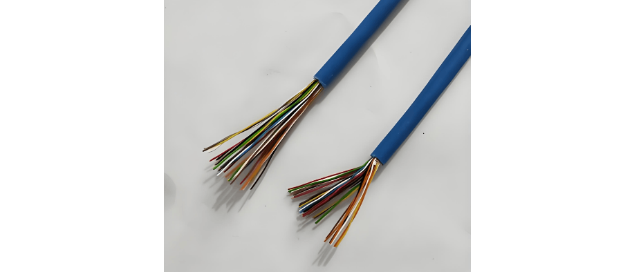
1.1 Cable Selection Matching Issues
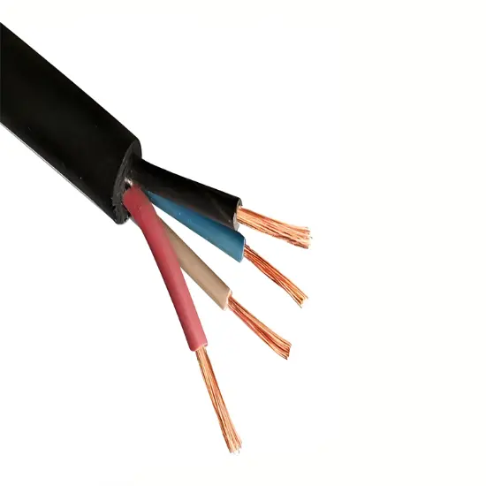
Structures like braided/foil - wound shielding in electromagnetic shielding cables, if mismatched with transmission frequency, cause characteristic impedance deviations, affecting signal stability/accuracy. Weather - resistant materials (fluoroplastic insulation, metal armoring) meet harsh environment needs but their high hardness/rigidity conflict with construction flexibility, risking insulation damage/armor breakage during bending/stretching, threatening installation quality.
1.2 Routing & Anti - interference Design Conflicts
Due to space constraints, when strong - current and weak - current lines are laid in parallel too closely, alternating electromagnetic fields from strong - current circuits interfere with weak - current signals via coupling, causing distortion/attenuation. Poorly isolated cross - layout in complex spaces boosts electromagnetic coupling between wire pairs, leading to crosstalk issues. Improper shielding grounding (not following single - point/equipotential connection) causes ground loop currents from potential differences, worsening interference and threatening communication system stability .
1.3 Construction Precision Challenges
Improper shielded cable termination damages shielding layers or causes insecure grounding, increasing grounding resistance, damaging shielding integrity, and allowing external interference/internal signal leakage, reducing shielding efficiency. Inadequate fireproof sealing (gaps from poorly filled fireproof mud) fails to block flames/smoke. Defective moisture - proof sealing (bubbles/uneven adhesive) lets moisture seep in, causing long - term insulation aging/conductor corrosion, endangering communication system reliability/safety.
2 Quality Control Points for Protective Space Communication Cable Installation
2.1 Cable Selection & Material Inspection
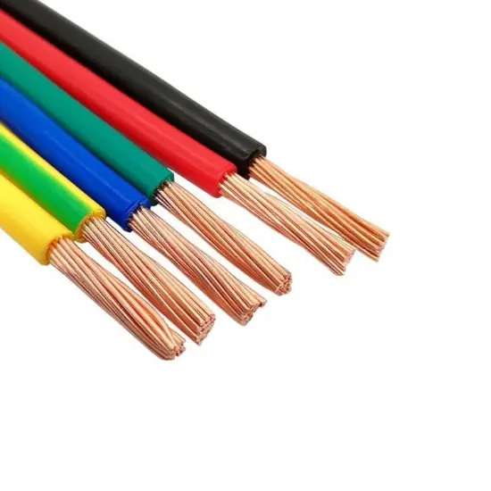
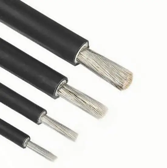
Cable selection should align with protective space needs: For electromagnetic shielding, use braided copper mesh cables (braiding density ≥ 90%) or double - shielded (foil - wound + braided) structures to ensure high - frequency anti - interference. For harsh environments (high temp, humidity), use polyimide insulated cables (temp resistance ≥ 200 °C) or IP68 - rated sealed oil - filled cables. Material inspection: Copper conductors must meet purity (≥ 99.99%), elongation (20% - 24%), and cross - section deviation (± 0.5%) standards. Shielding layers are tested for coverage, elongation at break (≥ 300%), and shielding resistance (≤ 0.5 Ω/m at 100 kHz) to ensure basic performance .
2.2 Routing Planning & Laying
Routing follows partition isolation/anti - interference principles: Strong - current, weak - current, and signal power cables are laid in separate trays (spacing ≥ 500 mm). Metal partitions at intersections block coupling. Sensitive signal cables use independent shielding pipes, avoiding parallel laying with power cables for > 10 m to reduce high - frequency interference. During laying, traction tension is controlled within 80% of cable allowable tension to prevent insulation damage .
2.3 Connection & Termination Quality Control
Shielded termination uses 360° full - circumference crimping, keeping contact resistance with connector shells ≤ 0.05 Ω, and passing 30 MHz - 1 GHz shielding attenuation tests (attenuation ≥ 60 dB) to ensure shielding integrity. For welding, use 3% - 5% silver - containing tin alloy solder, control temperature at 260 °C ± 10 °C, and cool for ≥ 30 s to ensure sound solder joints. Grounding uses single - end grounding at the signal source, keeping resistance < 1 Ω to avoid ground loops.
2.4 Protective Measures Implementation
For electromagnetic shielding, seal wall - penetrating holes with beryllium copper reeds + shielding flanges to match wall shielding efficiency and block leakage. Encapsulate cable joints in metal shielding boxes, connecting boxes to cable shields via welding/crimping, and fill gaps with conductive adhesive (conductivity ≥ 10⁴ S/m) for proper shielding.
In environmental protection: Fireproof sealing combines fire - resistant bags and mud (thickness ≥ 200 mm, meeting UL 1479). Moisture - proof sealing uses three - layer waterproof tape (butyl rubber, PVC, self - vulcanizing rubber) at joints, passing 24 - hour immersion tests (insulation resistance drop ≤ 10%). When crossing vibration areas, install metal hoses (10 Hz - 2000 Hz, amplitude ≤ 0.5 mm) with ≤ 500 mm spacing for mechanical protection against vibration - induced damage.
3 Conclusion
By analyzing core difficulties (electromagnetic shielding failure, poor environmental adaptability, construction precision issues) and discussing quality control points, protective space communication cable installation quality can be ensured. Future research can focus on intelligent monitoring (IoT - based real - time cable status evaluation, digital twin simulation platforms) to predict quality risks proactively, enhancing communication system safety/stability in protective spaces.