36S1000K-CC Transformer Price Calculator
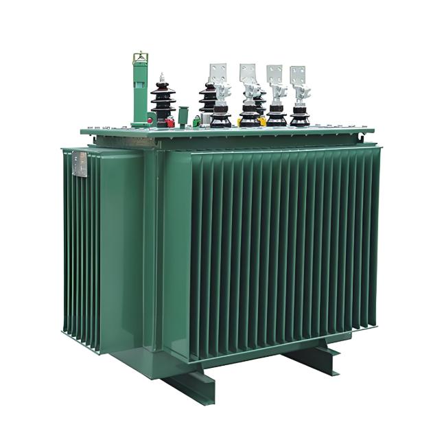
This tool is designed for power equipment manufacturers, buyers, and engineers to quickly estimate the manufacturing cost of oil-immersed distribution transformers based on international standards and real-world production data.
What Is Transformer Cost Estimation?
Transformer cost consists of three main components:
- Material cost: Copper, aluminum, silicon steel, insulating oil, etc.
- Manufacturing cost: Winding, core assembly, testing, etc.
- Regional & market factors: Labor, logistics, tariffs, exchange rates
This calculator estimates the theoretical manufacturing cost by inputting key parameters, helping with quoting, budgeting, and cost control.
Calculation Principle and Core Formula
The tool uses an industry-standard cost model that considers material usage and market prices:
Total Cost = Copper Cost + Aluminum Cost + Iron Core Cost + Oil Cost + Process Factor
Where:
- Copper Cost = Copper weight × Copper price
- Aluminum Cost = Aluminum weight × Aluminum price
- Iron Cost = Iron weight × Iron price
- Oil Cost = Oil volume × Oil price
- Process Factor = Total material cost × Price Factor
Weights of copper, aluminum, iron, and oil are estimated from rated capacity, voltage, frequency, and winding materials using empirical formulas aligned with IEC 60076 standard designs.
How to Use This Calculator?
- Select Standard: IEC 60076 or others (e.g., GB, IEEE)
- Select Country: Affects labor, tax, and logistics costs
- Enter Rated Capacity: in kVA (e.g., 25, 50, 100...)
- Set High-Voltage Winding: e.g., 30 kV
- Set Low-Voltage Winding: e.g., 1 kV
- Choose Frequency: 50 Hz or 60 Hz
- Select Winding Material: Copper (Cu) or Aluminum (Al)
- Input Current Market Prices:
- Copper price: $/t
- Aluminum price: $/t
- Iron price: $/t
- Oil price: $/t
- Set Price Factor: Default 1.0; adjust for regional differences (e.g., 1.2 for higher labor cost)
- Click [Calculate] to get the estimated cost
Typical Applications
- Transformer manufacturer cost calculation and quotation
- International buyer price comparison and supplier evaluation
- Project investment budget preparation
- Cost comparison between copper and aluminum windings
- Cost sensitivity analysis across different countries
- Educational and training purposes
Real-World Examples
Example 1: 25 kVA Transformer Cost in Afghanistan
- Standard: IEC 60076
- Country: Afghanistan
- Rated Capacity: 25 kVA
- H.V. Windings: 30 kV
- L.V. Windings: 1 kV
- Frequency: 50 Hz
- H.V. Winding Material: Cu
- L.V. Winding Material: Cu
- Copper Price: 11600 $/t
- Aluminum Price: 2920 $/t
- Iron Price: 448.6 $/t
- Oil Price: 1336 $/t
- Price Factor: 1.0
Estimated Result: Approximately $1,850 (including materials and process)
Example 2: Cost Change When Using Aluminum Winding
- Change L.V. winding material to Al only
- All other parameters unchanged
Estimated Result: Approximately $1,620 → Cost reduced by ~12.5%
Note: Although aluminum has lower unit price, its lower conductivity requires larger cross-section, so savings are limited but beneficial for cost-sensitive projects.
Why Choose Our Online Calculator?
- Works on desktop, mobile, and tablet
- Local calculation, no data upload
- Clear results with USD-based pricing
- Built-in explanations of cost structure
- Useful for comparing different configurations
Frequently Asked Questions (FAQ)
Q: Can this calculator give the actual factory price?
A: Not exactly, but it provides a reference baseline. Real prices also depend on brand, certification, shipping, taxes, and profit margin.
Q: How are copper and aluminum weights estimated?
A: Based on empirical formulas derived from IEC 60076 standard designs, considering capacity, voltage, and frequency. Accuracy is typically ±10%.
Q: Why does country affect the cost?
A: Labor, energy, tax, and logistics costs vary significantly by region. The "Price Factor" reflects these differences.
Q: Does it support other standards?
A: Currently supports IEC 60076. Future versions will add GB, IEEE, and other standards.
References & Standards
- IEC 60076-1: Power Transformers – Part 1: General
- GB 1094-2017: Chinese National Standard for Power Transformers
- "Transformer Design and Manufacturing" – China Machine Press