• Product
  • Suppliers
  • Manufacturers
  • Solutions
  • Free tools
  • Knowledges
  • Experts
  • Communities
Search


126kV GIS tubular insulation rod

  • 126kV GIS tubular insulation rod

Key attributes

Brand Switchgear parts
Model NO. 126kV GIS tubular insulation rod
Rated voltage 126kV
Series RN

Product descriptions from the supplier

Description

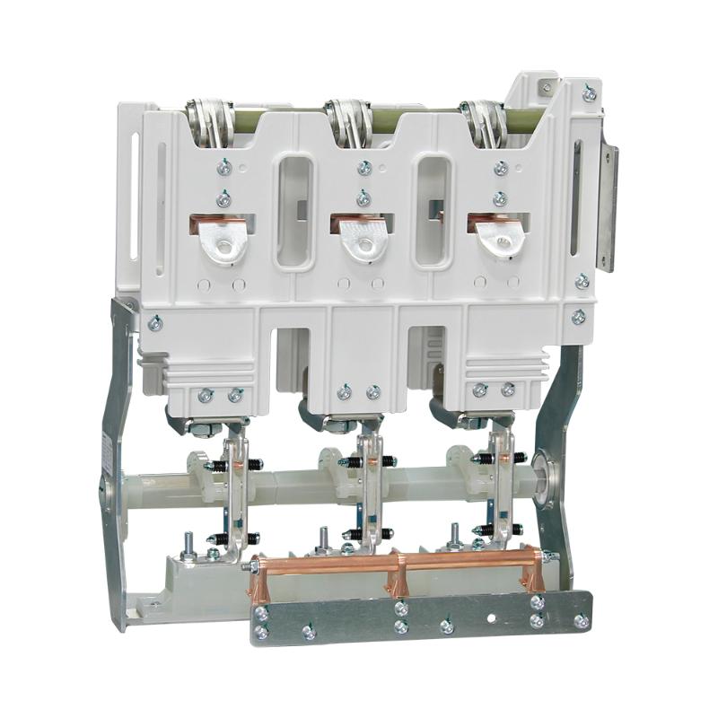
The 126kV GIS (gas insulated metal enclosed switchgear) tubular insulation rod is a key component in GIS circuit breakers, playing an important role in electrical insulation and mechanical operation. The following is a detailed introduction for you:
Structure and Materials
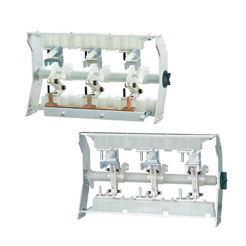
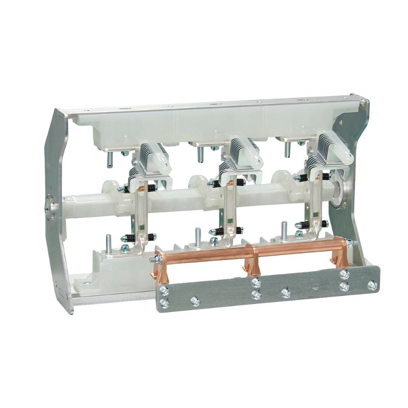
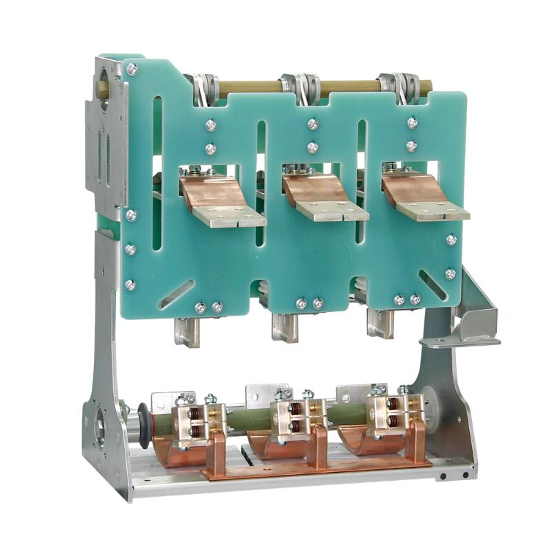
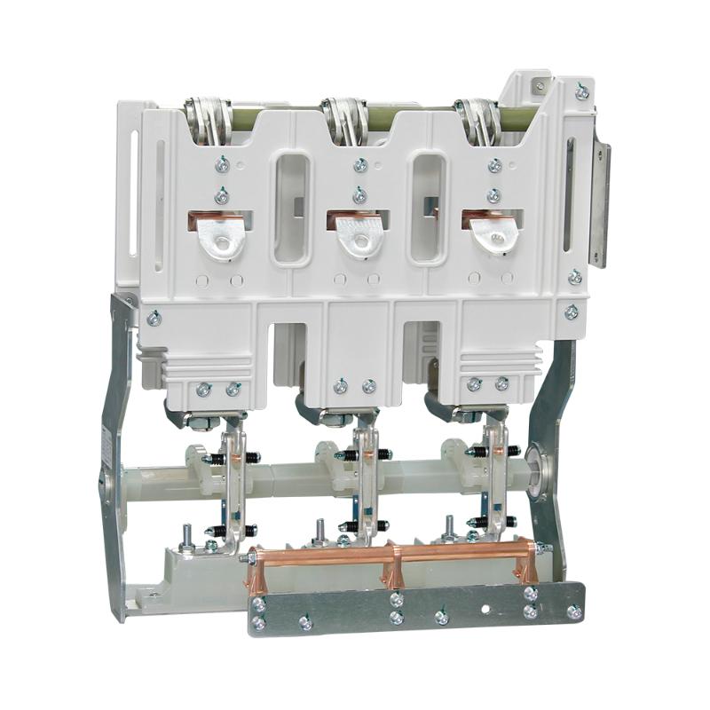
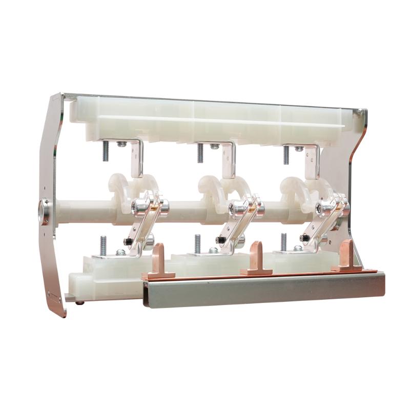
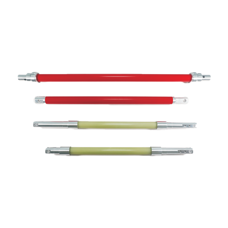
Structure: It usually adopts a tubular structure design, consisting of metal joints at both ends and an insulating tube in the middle. Metal joints are used to connect the operating mechanism and the moving contacts of circuit breakers, achieving force transmission; The insulation tube body undertakes the function of electrical insulation, ensuring the insulation performance between the operating mechanism and the live parts.
Material: The insulation tube body is generally made of glass fiber reinforced epoxy resin composite material. Glass fiber endows it with high mechanical strength, enabling it to withstand mechanical stresses such as tension and compression during operation; Epoxy resin provides excellent electrical insulation performance and chemical corrosion resistance. Metal joints are often made of materials such as copper alloys or stainless steel to ensure good conductivity and mechanical connection strength.
working principle
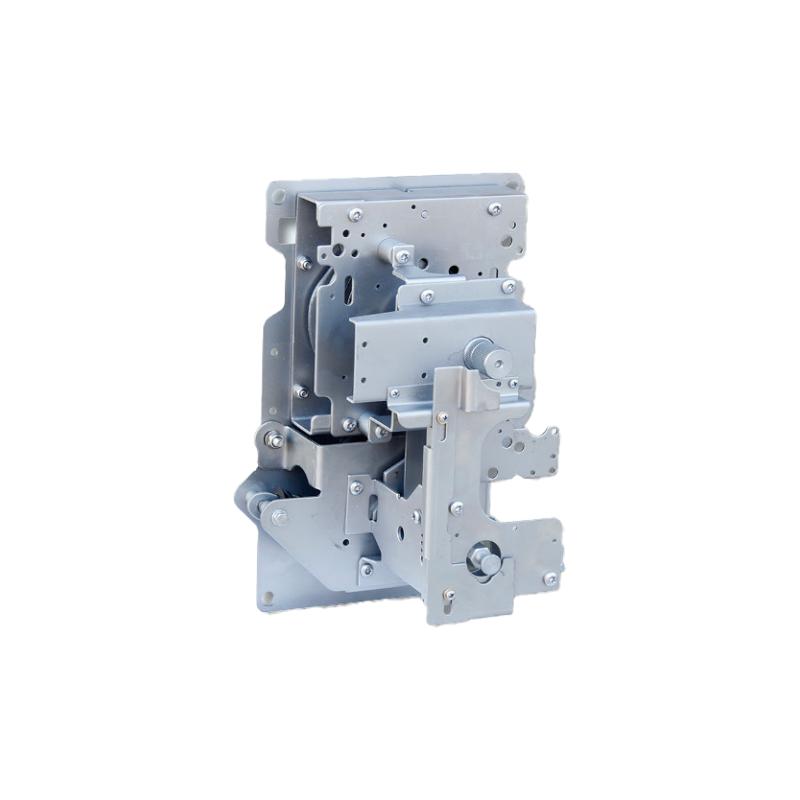
During the opening and closing operation of GIS circuit breakers, the operating mechanism applies tension or pressure to the insulation tube through the metal joint of the insulation rod, causing mechanical displacement of the insulation rod and driving the movement of the moving contact to achieve the opening or closing action of the circuit breaker. At the same time, the insulation tube of the insulation rod isolates the mechanical movement of the operating mechanism from the high-voltage conductive parts, preventing electric shock to the operators and ensuring the safe and reliable operation of the equipment.
Performance Requirements
Electrical performance: It needs to have excellent insulation performance and be able to withstand the rated voltage, power frequency withstand voltage, lightning impulse withstand voltage and other electrical test requirements of the 126kV system. It is usually required to have no flashover or breakdown phenomenon under the specified test voltage, and the partial discharge should also be controlled at an extremely low level, such as not exceeding a few picoku (pC).
Mechanical performance: It has high mechanical strength and good fatigue resistance to withstand the mechanical stress caused by frequent operation. For example, its tensile strength generally needs to reach several hundred megapascals, able to withstand tens of kilonewtons or even higher tensile forces, and its mechanical properties will not show significant decline after long-term operation cycles.
Environmental resistance: It can adapt to different environmental conditions, such as high temperature, low temperature, humidity, pollution, etc. In harsh environments, its insulation and mechanical properties remain stable and reliable.
Production and Testing
Production process: The insulation tube body is generally formed by extrusion molding. After impregnating the glass fiber with epoxy resin, it is extruded and cured through a mold to ensure dimensional accuracy and material uniformity; The connection between metal joints and insulation pipes is often achieved through processes such as adhesive bonding or mechanical crimping to ensure a firm connection and good contact.
Testing: During the production process and after the finished product, strict testing is required, including appearance inspection, size measurement, electrical performance testing (such as power frequency withstand voltage test, partial discharge test, etc.), mechanical performance testing (such as tensile test, fatigue test, etc.). Only insulation rods that meet the standard requirements in all indicators can be put into use.

Note: Customization with drawings is available

Know your supplier
Online store
On-time delivery rate
Response time
100.0%
≤4h
Company overview
Workplace: 1000m² Total staff: Highest Annual Export(usD): 300000000
Workplace: 1000m²
Total staff:
Highest Annual Export(usD): 300000000
Services
Business Type: Sales
Main Categories: Low Voltage Electrical Apparatus/Instrument meters/Production equipment/Tester/High Voltage Electrical Apparatus/Electrical fittings/Equipment Parts
Whole life care manager
Whole-life care management services for equipment procurement, use, maintenance, and after-sales, ensuring safe operation of electrical equipment, continuous control, and worry-free electricity consumption.
The equipment supplier has passed platform qualification certification and technical evaluation, ensuring compliance, professionalism, and reliability from the source.

Related Products

Related Knowledges

  • Faults and Handling of Single-phase Grounding in 10kV Distribution Lines
    Characteristics and Detection Devices for Single-Phase Ground Faults1. Characteristics of Single-Phase Ground FaultsCentral Alarm Signals:The warning bell rings, and the indicator lamp labeled “Ground Fault on [X] kV Bus Section [Y]” illuminates. In systems with a Petersen coil (arc suppression coil) grounding the neutral point, the “Petersen Coil Operated” indicator also lights up.Insulation Monitoring Voltmeter Indications:The voltage of the faulted phase decreases (in
    01/30/2026
  • Neutral point grounding operation mode for 110kV~220kV power grid transformers
    The arrangement of neutral point grounding operation modes for 110kV~220kV power grid transformers shall meet the insulation withstand requirements of transformer neutral points, and shall also strive to keep the zero-sequence impedance of substations basically unchanged, while ensuring that the zero-sequence comprehensive impedance at any short-circuit point in the system does not exceed three times the positive-sequence comprehensive impedance.For 220kV and 110kV transformers in new constructi
    01/29/2026
  • Why Do Substations Use Stones, Gravel, Pebbles, and Crushed Rock?
    Why Do Substations Use Stones, Gravel, Pebbles, and Crushed Rock?In substations, equipment such as power and distribution transformers, transmission lines, voltage transformers, current transformers, and disconnect switches all require grounding. Beyond grounding, we will now explore in depth why gravel and crushed stone are commonly used in substations. Though they appear ordinary, these stones play a critical safety and functional role.In substation grounding design—especially when multiple gr
    01/29/2026
  • Why Must a Transformer Core Be Grounded at Only One Point? Isn't Multi-Point Grounding More Reliable?
    Why Does the Transformer Core Need to Be Grounded?During operation, the transformer core, along with the metal structures, parts, and components that fix the core and windings, are all situated in a strong electric field. Under the influence of this electric field, they acquire a relatively high potential with respect to ground. If the core is not grounded, a potential difference will exist between the core and the grounded clamping structures and tank, which may lead to intermittent discharge.I
    01/29/2026
  • Understanding Transformer Neutral Grounding
    I. What is a Neutral Point?In transformers and generators, the neutral point is a specific point in the winding where the absolute voltage between this point and each external terminal is equal. In the diagram below, pointOrepresents the neutral point.II. Why Does the Neutral Point Need Grounding?The electrical connection method between the neutral point and earth in a three-phase AC power system is called theneutral grounding method. This grounding method directly affects:The safety, reliabilit
    01/29/2026
  • What’s the Difference Between Rectifier Transformers and Power Transformers?
    What is a Rectifier Transformer?"Power conversion" is a general term encompassing rectification, inversion, and frequency conversion, with rectification being the most widely used among them. Rectifier equipment converts input AC power into DC output through rectification and filtering. A rectifier transformer serves as the power supply transformer for such rectifier equipment. In industrial applications, most DC power supplies are obtained by combining a rectifier transformer with rectifier equ
    01/29/2026
Haven't found the right supplier yet? Let matching verified suppliers find you. Get Quotation Now
Haven't found the right supplier yet? Let matching verified suppliers find you.
Get Quotation Now
Send inquiry
+86
Click to upload file
Download
Get the IEE Business Application
Use the IEE-Business app to find equipment, obtain solutions, connect with experts, and participate in industry collaboration anytime, anywhere—fully supporting the development of your power projects and business.