| Brand | MV Switchgear Accessories |
| Model NO. | 12KV SF6 filling cabinet gas insulated electric incoming spring operating mechanism |
| Rated voltage | 12kV |
| Rated normal current | 630A |
| Rated frequency | 50/60Hz |
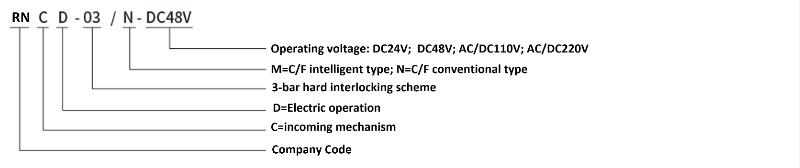
| Series | RNCD-03 |
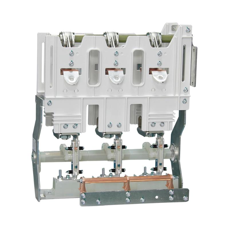
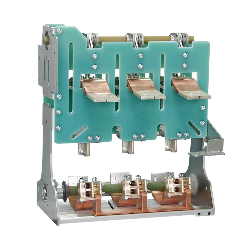
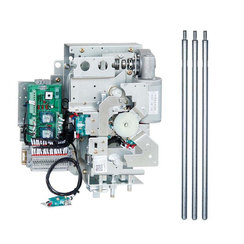
Inflatable cabinet mechanism Install and fix the mechanism cabinet, insert the mechanism specific handle into the operating shaft located at the upper part of the mechanism, rotate the handle clockwise by about 90 °, and release the energy when the mechanism spiral spring is compressed to the critical point of energy release. Under the power of energy release, push the load switch to close the main circuit. When electrically closing, power on the mechanism and provide a closing signal. The controller will automatically determine the opening and closing positions of the load switch and the status of each interlocking circuit. If the status of each circuit reaches the condition for closing, the controller will automatically start the mechanism motor to complete the main circuit closing of the load switch. At this time, the grounding function of the mechanism is locked, and grounding operation cannot be performed.
Instructions for use and operation
Closing operation:
Install and fix the mechanism cabinet, insert the mechanism specific handle into the operating shaft located at the upper part of the mechanism, rotate the handle clockwise by about 90 °, and release the energy when the mechanism spiral spring is compressed to the critical point of energy release. Under the power of energy release, push the load switch to close the main circuit. When electrically closing, power on the mechanism and provide a closing signal. The controller will automatically determine the opening and closing positions of the load switch and the status of each interlocking circuit. If the status of each circuit reaches the condition for closing, the controller will automatically start the mechanism motor to complete the main circuit closing of the load switch. At this time, the grounding function of the mechanism is locked, and grounding operation cannot be performed.
Opening operation:
When manually opening the switch, insert the mechanism specific handle into the operating shaft located at the upper part of the mechanism, rotate the handle counterclockwise by about 90 °, and release the energy when the mechanism spiral spring is compressed to the critical point of energy release. Push the load switch to complete the main circuit opening action under the release of energy power. When the electric circuit is disconnected, the user provides a disconnection signal, and the controller will automatically distinguish the on/off position of the load switch and the status of each interlocking circuit. If the status of each circuit reaches the condition for disconnection, the controller will start the motor of the mechanism to complete the disconnection of the main circuit of the load switch. Closing or grounding operations can be performed in the open state.
Grounding closing and opening:
Grounding closing: Insert the dedicated handle of the mechanism into the grounding operation shaft at the lower part of the mechanism, rotate it clockwise by about 90 °, and the grounding energy storage spring will release energy instantly when compressed past the midpoint to push the grounding switch to complete the grounding closing. At this time, the mechanism is interlocked and locked, and the main circuit cannot be closed.
Grounding disconnection: Insert the dedicated handle of the mechanism into the grounding operation shaft at the lower part of the mechanism, rotate it counterclockwise by about 90 °, and the grounding energy storage spring will release energy instantly when compressed past the midpoint to push the grounding switch to complete the grounding disconnection. At this time, the mechanism interlock is in the open state, and the load switch can be closed or opened.
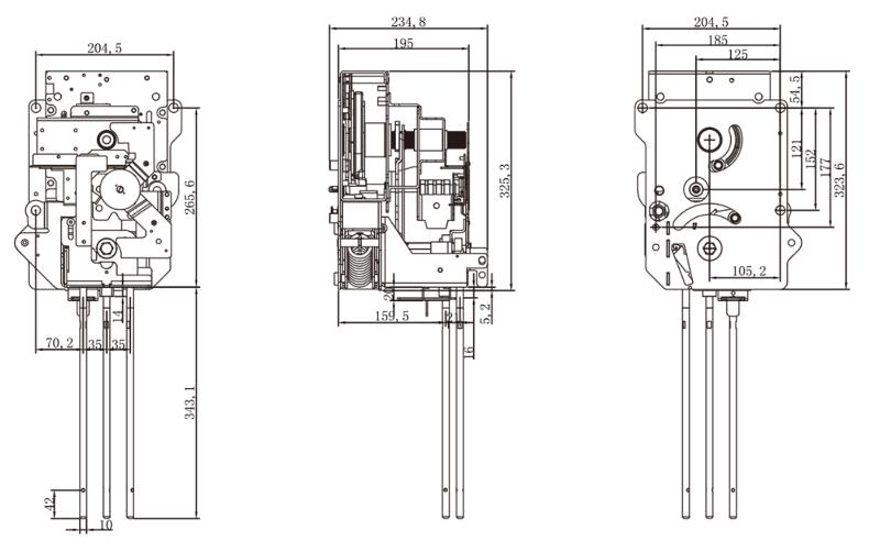
Installation dimensions