| Brand | Vziman |
| Model NO. | 33kV 34.5kV 35kV 36kV Three-phase Oil-immersed Power Distribution Transformer Original Manufacturer |
| Rated capacity | 1000kVA |
| Series | Distribution Transformer |
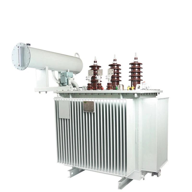
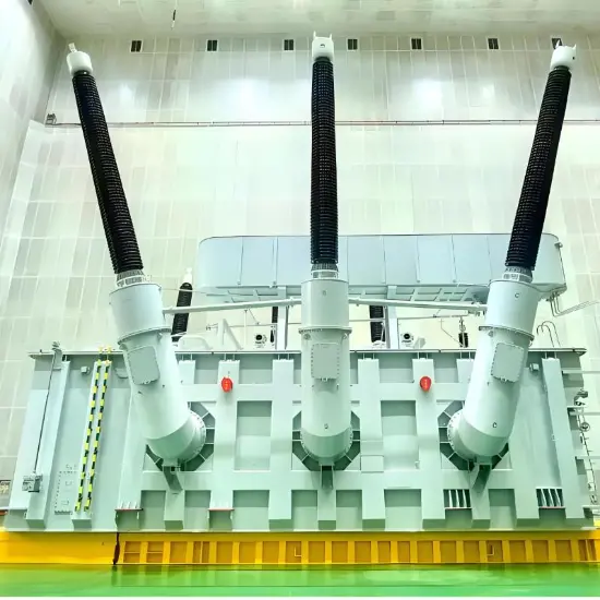
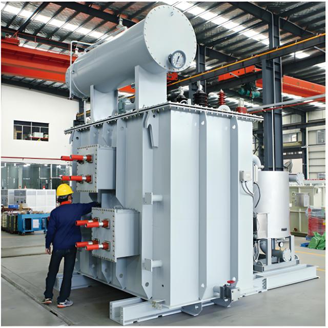
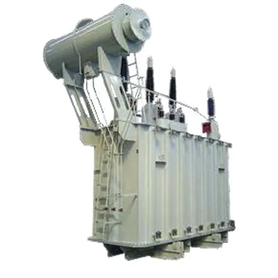
Product overview:
As a pioneer in China's power transformer industry, we have specialized in the R&D and manufacturing of power transformer equipment for decades, and established industry standards with core technologies.
This power transformer is fully compliant with international standards including IEC 60076-1, IEEE C57.12.00, ANSI C57.12.90, AS/NZS 60076.5 and EN 61558-1. It meets quality requirements and is widely adaptable to the operational needs of power grids in multiple overseas regions.
High reliability of operation verification in more than 50 countries and regions around the world.
Mainly used in 33kV distribution network, industrial and mining enterprises and civil building power supply and distribution system.
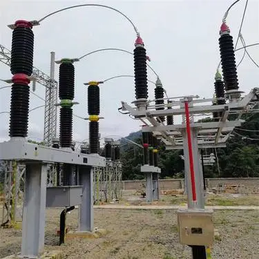
Roducts are mainly exported to Southeast Asia, the Middle East, Africa, South America and other countries and regions.
Standards: IEC 60076 series, IEC 6013, IEC 60214-1, IEC 60296; Gb1094-1996, GB/T6451-2008, GB/T7597-2007, etc.
The voltage classes of some of these Power Transformer include 6kV, 6.3kV, 6.6kV, 6.9kV, 7.2kV, 10kV, 10.5kV, 11kV, 11.5kV, 12kV, 13.2kV, 13.8kV, 14.5kV, 14.4kV, 15kV, 15.5kV, 15.6kV, 17.5kV, 20kV, 21.9kV, 22kV, 24kV, 30kV, 33kV, 33.5kV, 34.5kV, 35kV, 36kV, 38kV, 38.5kV, 40.5kV, 44kV, 45kV, 46kV, 66kV 69kV.72.5kV 88kV 110kV 115kV 123kV 125kV 126kV 132kV 138kV 145kV 150kV 154kV 161kV 170kV 220kV 225kV 230kV 245kV 275kV 330kV 345kV 363kV 380kV 400kV 500kV Power transformers of voltage ,and aboveand customization is available.
Product advantages
Leading technology
High pressure copper tape winding technology, improve lightning resistance.
Low voltage copper foil winding technology, high quality A class insulation material insulation.
Small magnetic leakage, high mechanical strength, strong short circuit resistance.
Iron core 45° full oblique joint step laminated structure.
The shell
Mitsubishi laser cutting machine and CNC punching, reducing, folding and other equipment to ensure the accuracy of processing.
ABB robot automatic welding, laser detection, to avoid leakage, qualified rate of 99.99998%.
Electrostatic spray treatment, 50 years of paint (coating corrosion resistance within 100h, hardness ≥0.4.
Fully sealed structure, maintenance-free and maintenance-free, normal operation life of more than 30 years.
The iron core
The core material is high quality cold rolled grain oriented silicon steel sheet with mineral oxide insulation (from Baowu Steel Group, China).
Minimize loss level, no-load current and noise by controlling the cutting and stacking process of silicon steel sheet.
The iron core is specially reinforced to ensure the transformer structure is firm during normal operation and transportation .
winding
Low voltage winding is made of high quality copper foil, excellent insulation resistance.
The high voltage windings are usually made of insulated copper wire, using the patented technology of Hengfengyou Electric.
Very good resistance to radial stress caused by short circuit.
High quality material
Baowu Steel Group production of silicon steel sheet.
High quality anaerobic copper from China.
CNPC (Kunlun Petroleum) High quality transformer oil (25#).
Other instructions
The low-voltage outgoing terminal is tinned copper bar.
The high-voltage outlet terminals are ring tinned bolts.
Default no-load voltage regulator NLTC (OLTC can be customized) tap switch 5 or 7.
Transformers above 630KVA are protected by gas relays.
Ordering instructions
Main parameters of transformer (voltage, capacity, loss and other main parameters).
Transformer operating environment (altitude, temperature, humidity, location, etc).
Other customization requirements (tap switch, color, oil pillow, etc).
The minimum order quantity is 1 sets, worldwide delivery within 7 days.
Normal delivery period of 30 days, worldwide fast delivery.
What is high-voltage copper strip winding technology?
Definition:
High - voltage copper - tape winding technology refers to the use of copper tape as the winding material in the manufacturing of high - voltage transformers and reactors. The copper tape is wound layer by layer around the iron core or the bobbin through mechanical or automated equipment to form the required high - voltage winding. This technology can ensure the uniformity and compactness of the winding and improve the electrical performance and mechanical strength of the equipment.
Technical Features:
High Conductivity: Copper tape has excellent electrical conductivity, which can effectively reduce the resistance loss of the winding and improve the efficiency of the equipment.
Mechanical Strength: Copper tape has relatively high mechanical strength and can withstand the impact of high voltage and large current, improving the reliability and service life of the equipment.
Uniformity: Through precise winding processes, the uniform distribution of each layer of copper tape can be ensured, reducing the problems of local overheating and non - uniform electric field.
Compactness: Copper - tape winding can achieve a higher winding density, making the equipment more compact in volume and saving space.
Insulation Performance: During the copper - tape winding process, insulating materials can be added between each layer of copper tape to ensure good electrical insulation performance.