| Brand | Switchgear parts |
| Model NO. | 40.5kV GIS Sf6 Break Switch Circuit Breaker for Gas Insulated Switchgear |
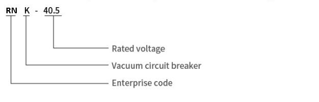
| Rated voltage | 40.5kV |
| Rated normal current | 630A |
| Rated short circuit breaking current | 25kA |
| Series | RNK-40.5 |
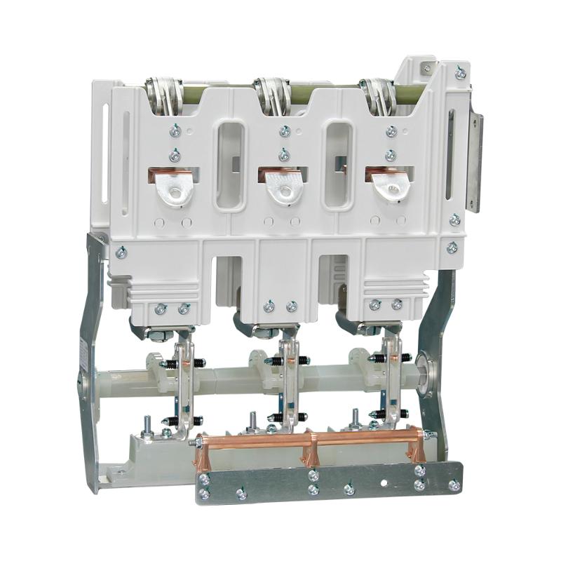
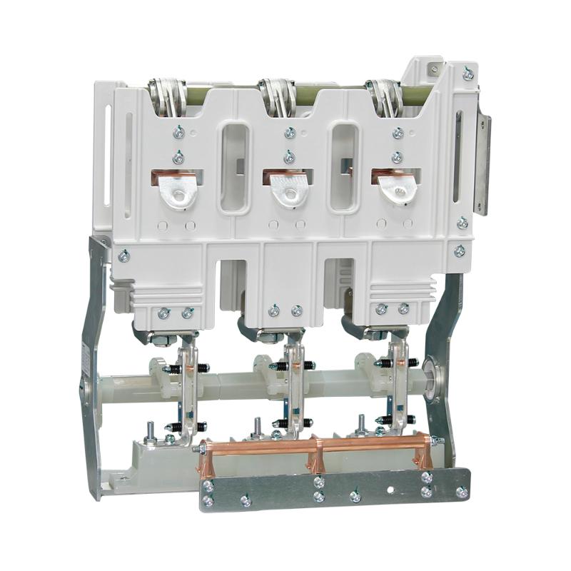
This 40.5kV circuit breaker is a core component of gas-insulated switchgear (GIS), utilizing SF6 gas for superior insulation and arc-quenching performance. Designed for medium-to-high voltage grids, it delivers fast, reliable breaking and switching operations to protect against overcurrents and short circuits.
Its compact, sealed structure minimizes footprint, resists environmental factors (dust, moisture, extreme temps), and reduces maintenance needs. Equipped with advanced mechanical interlocks and smart monitoring compatibility, it ensures safe, precise operation—critical for substations, urban power grids, and industrial facilities. Compliant with IEC 62271 and GB standards, it offers long service life and stable performance, making it a trusted choice for efficient grid management.
The main circuit of the high-voltage gas-insulated switchgear accessories is 630A-20kA (4S) and 25kA (3S), with a mechanical life of 10000 cycles. The current of the grounding circuit is 20kA (2S), and the mechanical life is 2000 cycles.
Considerations for the use of environmental conditions
The altitude is not more than 1000m, and the crack degree is not more than 8 degrees.Pollution level: ll
The environmental temperature of the product is -40 degrees ~+140 DEG C, therelative humidity is not greater than 90% per day, and the average is not more than90% per month;
The installation site of frequent and violent shock, water vapor, chemical corrosiondeposition, salt fog, dust, dirt and fire, which obviously affect the performance of themechanism, are not suitable for the installation of explosive dangerous installations.
Model composition and meaning
Main technical parameters
Serial number |
content |
Company |
technical parameter |
1 |
Main circuit resistance of circuit breaker |
UΩ |
≤30 |
2 |
Super |
mm |
2-3 |
3 |
Open distance |
mm |
19±1 |
4 |
bounce |
ms |
≤5 |
5 |
Mean speed of gate separation |
m/s |
1.4-2.0 |
6 |
Closing average speed |
m/s |
0.8-1.2 |
7 |
Three phases of switching off |
ms |
≤2 |
8 |
Closing three phases |
ms |
≤2 |
Outline and installation dimensions of circuit breaker
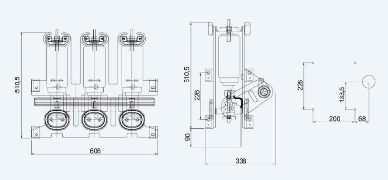
It is a dedicated medium-voltage electrical component installed in 40.5kV SF6 gas-insulated cabinets, adopting vacuum arc-extinguishing technology to realize on-off control and fault protection of the medium-voltage power distribution circuit. Its core functions include 3 key points: ① Circuit protection: Reliably cut off normal load current and short-circuit fault current (≥31.5kA) to avoid equipment damage caused by faults; ② Arc-extinguishing performance: Use vacuum as the arc-extinguishing medium, with fast arc-extinguishing speed, no environmental pollution, and stable performance under SF6 gas insulation; ③ Safety interlocking: Realize mechanical interlock with the cabinet door, isolation switch and PT (potential transformer) isolation switch to avoid misoperations such as live maintenance and closing with grounding. It is widely used in 40.5kV medium-voltage distribution systems such as power grids, industrial and mining enterprises and commercial parks.