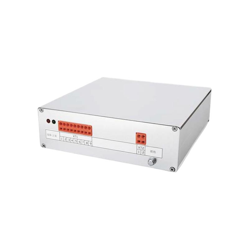
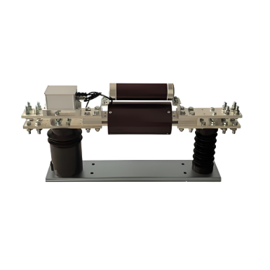
Circuit breaker driver module
Key attributes
| Brand | Wone Store |
| Model NO. | Circuit breaker driver module |
| Rated operating voltage for CB | DC 110V |
| Series | MD |
Product descriptions from the supplier
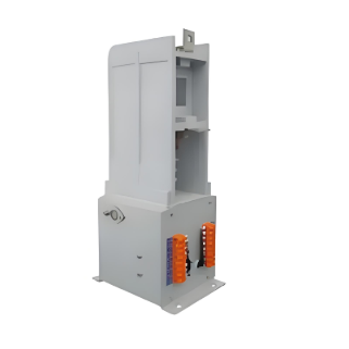
The drive module is used in conjunction with the circuit breaker, serving as a control and online monitoring device for the circuit breaker system. The housing of the drive module is made of aluminum alloy, which can effectively shield electromagnetic interference, including five unit circuits:
Switching power supply unit: Converts the external auxiliary power supply into the power source used by the internal circuit.
Charging circuit unit: Stores electrical energy for the closing and opening capacitors.
Discharge circuit unit: Injects positive excitation current or reverse demagnetization current into the excitation coil of the circuit breaker mechanism to magnetize or demagnetize the mechanism.
I/O interface unit: It is used to receive the opening and closing commands as well as the input of the circuit breaker status.
Control Unit: Monitors and controls the operation of the entire circuit breaker.
Basic function
Provide the excitation current for closing operation
Provide de-magnetizing current for opening operation
On-line monitoring
Alarm for abnormal movement of auxiliary switch
Manual trip alarm
Anti-jump and locking function
The drive module itself has a function of anti-jump locking
application
Driving MS Series circuit-breaker
Technology parameters
No. |
Item |
Unit |
MD-01 |
MD-02 |
MD-03 |
Rated operating parameter |
|||||
1 |
Rated operating cycle |
-- |
O-0.3s-CO-15s-CO |
||
2 |
Maximum number of operations per hour |
Times |
100 |
||
3 |
Service Voltage |
V |
DV24 |
DV48 |
AC/DC100/220 |
4 |
Auxiliary Power supply voltage Range |
% |
80-120 |
||
Power consumption |
|||||
5 |
Capacitor charge power consumption |
W |
20 |
||
6 |
Stand-by power consumption |
W |
< 5 |
||
Time response |
|||||
7 |
Capacitor charging time after first power-on |
s |
< 20 |
||
8 |
Capacitor charge time after standard operating cycle |
s |
< 10 |
||
Dielectric strength |
|||||
9 |
Power frequency withstand voltage |
kV |
2 |
||
10 |
Impulse withstand voltage |
kV |
40us/50us/ 0.5 J (IEC 60 255-5) |
||
11 |
Insulation resistance |
MΩ |
> 5 |
||
Relay contactor |
|||||
12 |
Relay contact breaking capability |
ms |
250V AC16A/250V DC15A |
||
Open and close dry contact |
|||||
13 |
Open and close command accept time |
ms |
> 12 |
||
14 |
Voltage of the dry contact port on the control module |
V |
15 |
||
EMC |
|||||
15 |
Electrical fast pulse immunity level |
-- |
IEC61000-4-4 Ⅳ |
||
16 |
Oscillation wave immunity level |
-- |
IEC61000-4-12 Ⅲ |
||
17 |
Surge immunity level |
-- |
IEC61000-4-4 Ⅳ |
||
18 |
Pulse magnetic field immunity level |
-- |
IEC61000-4-4 Ⅴ |
||

Related Products


Related Knowledges
-
 Intelligent Grounding Transformers for Island Grid Support1. Project BackgroundDistributed photovoltaic (PV) and energy storage projects are developing rapidly across Vietnam and Southeast Asia, yet face significant challenges:1.1 Grid Instability:Vietnam's power grid experiences frequent fluctuations (particularly in northern industrial zones). In 2023, coal power shortages triggered large-scale blackouts, resulting in daily losses exceeding USD 5 million. Traditional PV systems lack effective neutral grounding management capabilities, making equipmen12/18/2025
 -
 Commissioning Test Procedures for Oil-Immersed Power TransformersTransformer Testing Procedures and Requirements1. Non-Porcelain Bushing Tests1.1 Insulation ResistanceSuspend the bushing vertically using a crane or support frame. Measure the insulation resistance between the terminal and the tap/french using a 2500V megohmmeter. The measured values should not significantly deviate from factory values under similar environmental conditions. For capacitive-type bushings rated 66kV and above with tap bushings, measure the insulation resistance between the "small12/17/2025
 -
 Quality Standards for Core Maintenance of Power TransformersTransformer Core Inspection and Assembly Requirements The iron core should be flat with intact insulation coating, tightly stacked laminations, and no curling or waviness at the edges of silicon steel sheets. All core surfaces must be free of oil, dirt, and impurities. There should be no short circuits or bridging between laminations, and joint gaps must meet specifications. Good insulation must be maintained between the core and upper/lower clamping plates, square iron pieces, pressure plates,12/17/2025
 -
 Power Transformers: Short Circuit Risks, Causes, and Improvement MeasuresPower Transformers: Short Circuit Risks, Causes, and Improvement MeasuresPower transformers are fundamental components in power systems that provide energy transmission and are crucial induction devices ensuring safe power operation. Their structure consists of primary coils, secondary coils, and an iron core, utilizing the principle of electromagnetic induction to alter AC voltage. Through long-term technological improvements, the reliability and stability of power supply have continuously enha12/17/2025
 -
 8 Key Measures to Reduce Partial Discharge in Power TransformersGrowing Requirements for Power Transformer Cooling Systems and the Function of CoolersWith the rapid development of power grids and the increase in transmission voltage, power grids and electricity users are demanding increasingly higher insulation reliability for large power transformers. Since partial discharge testing is non-destructive to insulation yet highly sensitive, effectively detecting inherent defects in transformer insulation or safety-threatening defects generated during transporta12/17/2025
 -
 General Requirements and Functions of Power Transformer Cooling SystemsGeneral Requirements for Power Transformer Cooling Systems All cooling devices shall be installed in accordance with the manufacturer's specifications; The cooling system with forced oil circulation must have two independent power supplies with automatic switching capability. When the working power supply fails, the standby power supply shall be automatically activated while emitting audible and visual signals; For transformers with forced oil circulation, when a faulty cooler is disconnected, a12/17/2025
Related Solutions
-
 Dedicated Vacuum Contactor Solution for Port Shore Power SystemsI. Background and ChallengesShore power systems have become core technical equipment for ports to reduce carbon emissions and noise pollution. However, these systems face two major challenges in the harsh operational environment of ports:Severe Environmental Corrosion: High humidity and salt spray in port areas cause serious corrosion to metal components and enclosures of electrical equipment, significantly impacting electrical lifespan and operational reliability.High Switching Requirements:09/13/2025
 -
 ABB Vacuum Contactor KC2 Power Supply System Technical Transformation PlanIssue OverviewThe 10kV air compressor starting system of a company utilizes the ABB vacuum contactor KC2 as the control component for the operating circuit. The dedicated wide-voltage power supply module paired with this contactor presents the following issues:Frequent failures: The power supply module fails to properly transition the voltage from 300V to 12V, resulting in fuse blowouts.Poor heat dissipation: Enclosed installation of the module leads to insufficient heat dissipation, acceler09/13/2025
 -
 Solution for Medium-Voltage Motor Control and Protection Using Vacuum Contactor-Fuse (VCF) in a Coal Conveying System1.Project BackgroundA coal conveying system comprises 15 belt conveyors driven by medium-voltage motors. The system operates under complex conditions, with motors often subjected to heavy loads and frequent starts. To address these challenges and achieve effective control and reliable protection during motor startup, the project comprehensively adopts Vacuum Contactor-Fuse (VCF) combination devices for the 6kV medium-voltage motor power distribution. This solution details the technical features,09/13/2025


