| Brand | ROCKWILL |
| Model NO. | Customization 66kV 88kV 110kV 132kV Three Phase Z-type winding Oil-Immersed Earthing Transformer source manufacturer |
| Rated voltage | 66kV |
| Phases | Three-phase |
| Series | JDS |
Product Overview
As a pioneer and the first dedicated original equipment manufacturer (OEM) in China's neutral grounding transformer industry, we have laid the original benchmark for the industry's development with our profound technical strength accumulated through decades of intensive cultivation. From the independent R&D of core technologies to large-scale mass production, we have built a full-process independently controllable system. Relying on our stable and leading product performance and unparalleled reliability, we have become a preferred partner in the field of power grid construction.
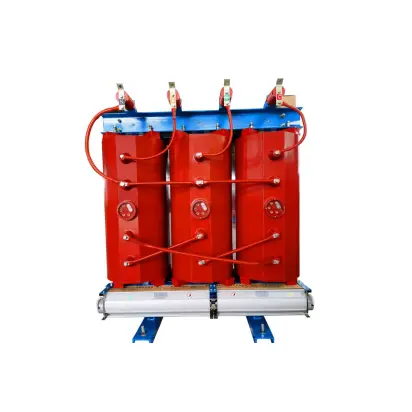
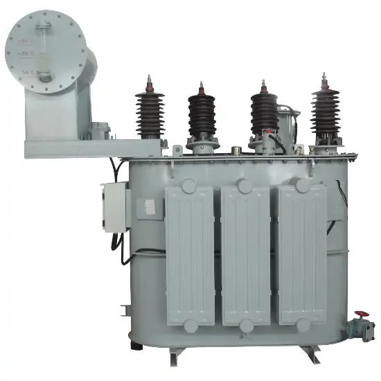
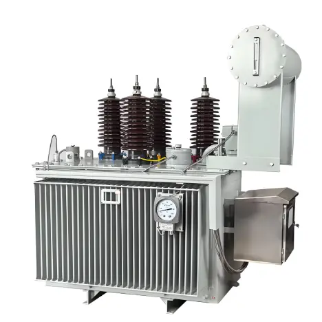
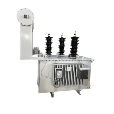
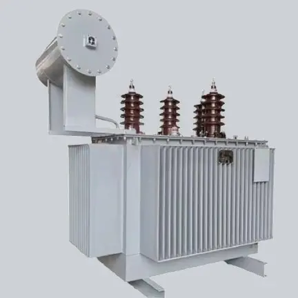
Rockwill delivers reliable and high-performance earthing transformers designed for 66kV power systems. Our oil-immersed transformers are engineered to provide stable neutral grounding solutions while ensuring operational safety and system protection. Manufactured in compliance with international standards including IEC and GB, these transformers incorporate premium materials and rigorous quality control throughout production.
Basic Info.
Some of these earthing transformers cover voltage levels including:3.3kV / 6kV / 11kV / 15kV / 20kV / 22kV / 30kV / 33kV / 34.5kV / 36kV / 44kV / 66kV / 88kV / 110kV / 132kV / 145kV / 150kV / 220kV / 275kV / 330kV / 400kV, etc. The current withstand time ranges from 1s, 2s, 3s, 5s, 6s, 8s, 9s, 10s, 30s, 60s, 1hour to 2hours, and customization is available.
Parameter |
Detail |
Parameter |
Details |
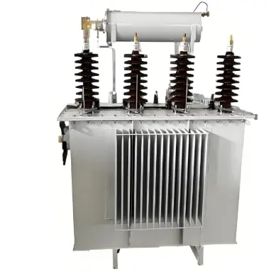
Cooling Method |
Oil-Immersed Type Transformer |
Core |
Core-type Transformer |
Certification |
ISO9001 |
Usage |
Power Transformer |
Frequency Characteristics |
Power Frequency |
Shape of Core |
Ring |
Brand |
Rockwill |
Item |
3 Phase Oil Type Earthing 6kv Power Transformer |
Primary Voltage |
66kv |
Secondary Voltage |
0.4kv |
Rating Capacity |
350kVA |
Transformer |
66kv Power Transformer |
Iron Core |
Wounded Core |
Coil Structure |
Isolation |
Loss |
Low Losses |
Tank Design |
Sealed |
Specification |
CTQC type tested |
Transport Package |
Wooden Case |
Origin |
Zhejiang China |
Trademark |
Rockwill |
Key Features
Voltage Class: 66kV system voltage (200 BIL)
Capacity Range: Standard units from 100kVA to 10,000kVA
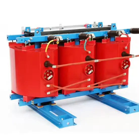
Winding Configuration: Optimized zigzag (ZNyn) design
Cooling System: ONAN/OFAF cooling options
Insulation: Mineral oil or synthetic ester fluid
Construction:
Corrugated tank or radiator cooling
Hermetically sealed or conservator tank options
CRGO silicon steel core
Copper/aluminum windings
Technical Advantages
Enhanced Safety: Built-in Buchholz relay and pressure relief device
Low Impedance: Zero-sequence impedance <15Ω for effective fault current management
Durability: Corrosion-resistant paint system for outdoor installations
Efficiency: Reduced no-load losses through optimized core design
Flexibility: Off-circuit tap changer (±5% in 2.5% Steps)
Typical Applications
Utility Networks:
Neutral grounding for 66kV transmission systems
Arc suppression coil connections
Resistance grounding systems
Industrial Plants:
Petrochemical facilities
Mining operations
Steel manufacturing plants
Renewable Energy:
Wind farm collector stations
Solar PV substations
Hydroelectric plants
Performance Specifications
Temperature Range: -30°C to +40°C Ambient
Humidity: ≤95% Monthly Average
Altitude: Up to 2000m ASL
Sound Level: ≤75dB at 1m
Efficiency: ≥99.2% at Full Load
Testing Protocol
All units undergo comprehensive testing including:
Zero sequence impedance measurement
Induced overvoltage test (260Hz)
Lightning impulse test (350kV)
Temperature rise test (65K max.)
Oil dielectric strength test (≥50kV)
Service Conditions
Suitable for indoor/outdoor installation
Wind resistant up to 35m/s
Non-explosive environments
Seismic capability: 0.3g horizontal acceleration
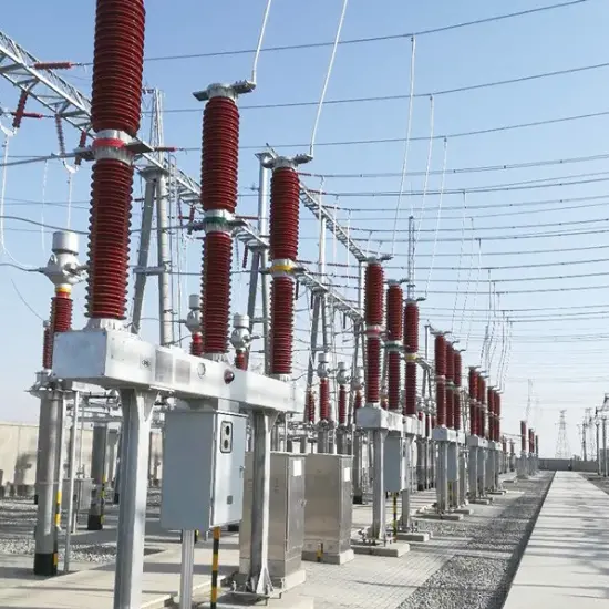
Application Fields
66kV/88kV/110kV/132kV Power Distribution Network Construction
New Energy Power Plants (e.g., Wind Power/Photovoltaic)
Power Distribution Stations in Large Industrial Parks
Railway Traction Power Supply Systems
Urban Power Grid Upgrading and Renovation Projects
High-Voltage Power Supply Systems for Industrial and Mining Enterprises
Grounding Protection Projects of Regional Substations
The differences between the two stem from the essential difference in functional positioning, specifically reflected in three aspects: ① Different core functions: ordinary power transformers focus on voltage transformation and energy transmission, while earthing/grounding transformers focus on constructing neutral points and providing fault current paths; ② Different capacity calibration: ordinary power transformers are marked with continuous operating capacity (long-term load capacity), while earthing/grounding transformers are marked with short-time rated capacity (capacity that can be carried within a specified time based on fault current and withstand time, such as 30 seconds); ③ Different winding designs: earthing/grounding transformers mostly adopt special winding structures such as zigzag (ZN), while ordinary power transformers mainly use conventional windings such as star and delta, and earthing/grounding transformers usually have no traditional voltage transformation ratio.
An earthing/grounding transformer is a special type of transformer that artificially creates a neutral point for ungrounded or low-current grounded power systems. It constructs a grounding circuit through a specific winding design, with two core functions: first, to provide a low-impedance path for zero-sequence current in the system, ensuring that the fault current reaches the operating threshold of the relay protection device when a single-phase ground fault occurs, enabling rapid fault location and isolation; second, to maintain system voltage balance, suppress excessive voltage rise of non-fault phases during faults, and protect the insulation safety of power grid equipment. Unlike ordinary power transformers, its core function is to "construct a grounding circuit" rather than "voltage transformation", and it is usually designed according to short-time load capacity instead of continuous operating capacity.