• Product
  • Suppliers
  • Manufacturers
  • Solutions
  • Free tools
  • Knowledges
  • Experts
  • Communities
Search


Integrated Transformer Testing Device

  • Integrated Transformer Testing Device

Key attributes

Brand Switchgear parts
Model NO. Integrated Transformer Testing Device
type Integrated testing platform
Series HB2819BJ

Product descriptions from the supplier

Description

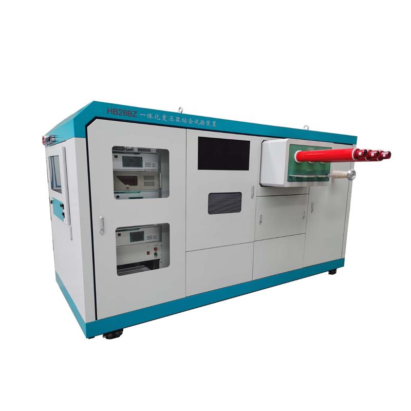
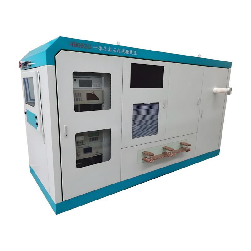
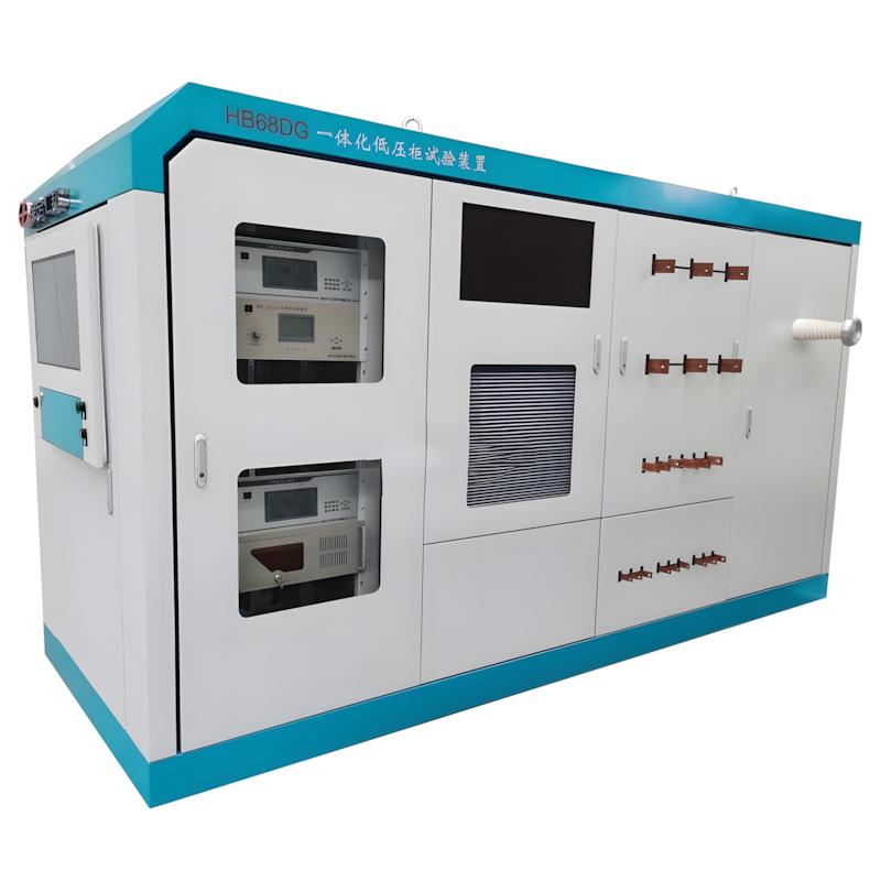
To facilitate mobility and reduce equipment footprint, we have developed an integrated transformer testing device. This device is capable of conducting factory tests and temperature rise tests on transformers, making it an ideal equipment for efficient testing of small capacity distribution transformers.

Features

It can complete direct resistance and transformation ratio tests through a single wiring, equipped with an automatic short-circuit device, and can also complete load tests simultaneously
One wiring can complete the no-load test and induction withstand voltage test
Equipped with HB6301 humidity meter and electric short-circuit device, it can automatically perform temperature rise test
The experimental equipment is equipped with Fuma wheels for easy mobility
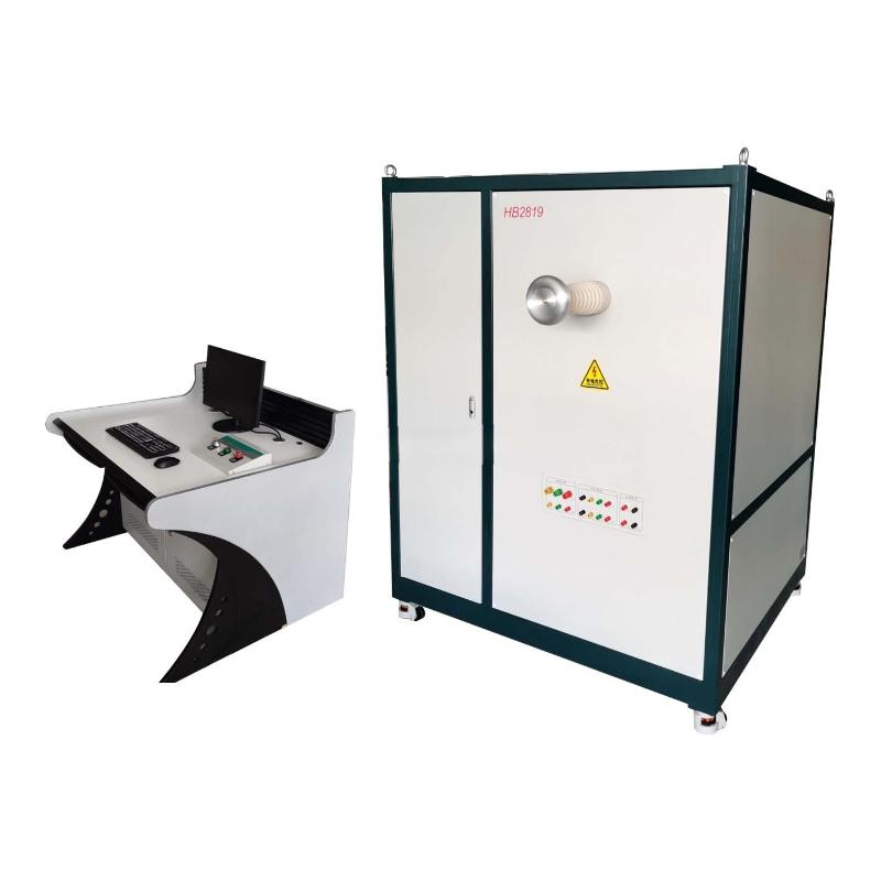
The experimental system is equipped with an automatic control console, which is easy to connect and move around
According to the sample specifications, configure a sine wave power supply and compensation capacity.

Technical Parameters

Test equipment

Model

Technical Parameters

DC resistance test unit

HB5851

Test current automatic: 5mA, 40mA, 200mA, 1A,5A,10A

Measurement range and accuracy:

 5mA:50Ω~50KΩ±(0.5%+2 )、40mA:500mΩ~250Ω±(0.2%+2 )、

 200mA:100mΩ~50Ω、1A:5mΩ~10Ω、5A:2mΩ~2Ω、

 10A:0.5mΩ~800mΩ

Minimum resolution 0.1 μΩ

Insulation resistance test unit

HB5805

Output voltage 100V,250V,500V,1000V,2500V,5000V

short circuit current: 5mA

Voltage display error: ±5%±3dgt (25℃)

Variable ratio group test unit

HB6605D

Measurement range: 0.9~10000,

measurement accuracy: ±0.2%

power analyzer

HB2000

Measuring voltage range: 50V,100V,250V,500V (phase voltage),

voltage measurement error: ± (0.05% reading +0.05% range)

Measuring current range: 1A,5A,10A,20A,50A,100A

Current measurement error: ±(0.05% reading +0.05% range),

power measurement error: ±(0.1% reading +0.1% range) (cosφ>0.2)

Three-phase sinusoidal wave frequency conversion test power supply

HB28YZ

Rated capacity: 20kVA,

output voltage: 600,850V,

output frequency: 50-200 (Hz)

testing transformer

YDQ-5/50

Rated capacity: 5 kVA,

output voltage: 50kV

Voltage divider

FC-50

Rated voltage: 50kV,

measurement accuracy 1.5%

Compensation capacitor banks

HB2819W

Rated voltage: 690V,

automatic switching

test-bed

HB2819

Industrial control machine control,

with transformer comprehensive test software system

FAQ
Q: What advantages does a Transformer Integrated Test Device have over traditional split-type testing instruments?
A:
Compared with split instruments that require separate wiring for each test item, it has the following core advantages:
 
  1. High efficiency & error reduction: One-time wiring completes 8+ test items, reducing wiring time by 60% and avoiding human errors caused by repeated disconnection and connection;
  2. Full automation: Supports one-click automatic testing and unattended operation, no need for manual range switching, reducing labor costs by 40%–50%;
  3. High precision & traceability: Adopts 16-bit high-speed ADC and digital filtering technology, data can be traced to national metrology standards, meeting factory certification requirements;
  4. Dual-use for laboratory & field: Portable models with IP52 protection are suitable for on-site substation maintenance; bench-top/ cabinet models are designed for mass production testing in factories;
  5. Intelligent fault diagnosis: Built-in fault model library, automatically identifies core grounding, winding deformation, and OLTC contact ablation issues, providing data support for condition-based maintenance
Q: What safety precautions should be followed when using the Transformer Integrated Test Device?
A:
Strictly abide by the following specifications to avoid electrical accidents and equipment damage:
 
  1. Electric shock prevention: Do not touch internal components when the device is powered on; wear insulated gloves during wiring and maintenance; ensure reliable grounding (ground resistance < 4Ω);
  2. High-voltage safety: During withstand voltage tests, strictly follow the operating procedures; cut off the power immediately in case of abnormal phenomena such as sparks and noise;
  3. Equipment protection: Avoid severe vibration during transportation (especially for portable models); store the device in a dry, ventilated room to prevent dampness;
  4. Waste disposal: Dispose of old batteries and damaged components in accordance with local environmental regulations; do not discard them as household waste.
Know your supplier
Online store
On-time delivery rate
Response time
100.0%
≤4h
Company overview
Workplace: 1000m² Total staff: Highest Annual Export(usD): 300000000
Workplace: 1000m²
Total staff:
Highest Annual Export(usD): 300000000
Services
Business Type: Sales
Main Categories: Low Voltage Electrical Apparatus/Instrument meters/Production equipment/Tester/High Voltage Electrical Apparatus/Electrical fittings/Equipment Parts
Whole life care manager
Whole-life care management services for equipment procurement, use, maintenance, and after-sales, ensuring safe operation of electrical equipment, continuous control, and worry-free electricity consumption.
The equipment supplier has passed platform qualification certification and technical evaluation, ensuring compliance, professionalism, and reliability from the source.

Related Products

Related Knowledges

  • Faults and Handling of Single-phase Grounding in 10kV Distribution Lines
    Characteristics and Detection Devices for Single-Phase Ground Faults1. Characteristics of Single-Phase Ground FaultsCentral Alarm Signals:The warning bell rings, and the indicator lamp labeled “Ground Fault on [X] kV Bus Section [Y]” illuminates. In systems with a Petersen coil (arc suppression coil) grounding the neutral point, the “Petersen Coil Operated” indicator also lights up.Insulation Monitoring Voltmeter Indications:The voltage of the faulted phase decreases (in
    01/30/2026
  • Neutral point grounding operation mode for 110kV~220kV power grid transformers
    The arrangement of neutral point grounding operation modes for 110kV~220kV power grid transformers shall meet the insulation withstand requirements of transformer neutral points, and shall also strive to keep the zero-sequence impedance of substations basically unchanged, while ensuring that the zero-sequence comprehensive impedance at any short-circuit point in the system does not exceed three times the positive-sequence comprehensive impedance.For 220kV and 110kV transformers in new constructi
    01/29/2026
  • Why Do Substations Use Stones, Gravel, Pebbles, and Crushed Rock?
    Why Do Substations Use Stones, Gravel, Pebbles, and Crushed Rock?In substations, equipment such as power and distribution transformers, transmission lines, voltage transformers, current transformers, and disconnect switches all require grounding. Beyond grounding, we will now explore in depth why gravel and crushed stone are commonly used in substations. Though they appear ordinary, these stones play a critical safety and functional role.In substation grounding design—especially when multiple gr
    01/29/2026
  • Why Must a Transformer Core Be Grounded at Only One Point? Isn't Multi-Point Grounding More Reliable?
    Why Does the Transformer Core Need to Be Grounded?During operation, the transformer core, along with the metal structures, parts, and components that fix the core and windings, are all situated in a strong electric field. Under the influence of this electric field, they acquire a relatively high potential with respect to ground. If the core is not grounded, a potential difference will exist between the core and the grounded clamping structures and tank, which may lead to intermittent discharge.I
    01/29/2026
  • Understanding Transformer Neutral Grounding
    I. What is a Neutral Point?In transformers and generators, the neutral point is a specific point in the winding where the absolute voltage between this point and each external terminal is equal. In the diagram below, pointOrepresents the neutral point.II. Why Does the Neutral Point Need Grounding?The electrical connection method between the neutral point and earth in a three-phase AC power system is called theneutral grounding method. This grounding method directly affects:The safety, reliabilit
    01/29/2026
  • What’s the Difference Between Rectifier Transformers and Power Transformers?
    What is a Rectifier Transformer?"Power conversion" is a general term encompassing rectification, inversion, and frequency conversion, with rectification being the most widely used among them. Rectifier equipment converts input AC power into DC output through rectification and filtering. A rectifier transformer serves as the power supply transformer for such rectifier equipment. In industrial applications, most DC power supplies are obtained by combining a rectifier transformer with rectifier equ
    01/29/2026
Haven't found the right supplier yet? Let matching verified suppliers find you. Get Quotation Now
Haven't found the right supplier yet? Let matching verified suppliers find you.
Get Quotation Now
Send inquiry
+86
Click to upload file
Download
Get the IEE Business Application
Use the IEE-Business app to find equipment, obtain solutions, connect with experts, and participate in industry collaboration anytime, anywhere—fully supporting the development of your power projects and business.