• Product
  • Suppliers
  • Manufacturers
  • Solutions
  • Free tools
  • Knowledges
  • Experts
  • Communities
Search


RMRTBB Medium and High Voltage Reactive Power Compensation Cabinet

  • RMRTBB Medium and High Voltage Reactive Power Compensation Cabinet
  • RMRTBB Medium and High Voltage Reactive Power Compensation Cabinet
  • RMRTBB Medium and High Voltage Reactive Power Compensation Cabinet

Key attributes

Brand Rw Energy
Model NO. RMRTBB Medium and High Voltage Reactive Power Compensation Cabinet
Rated voltage 6/10/35kV
Rated frequency 50Hz
Series RMRTBB

Product descriptions from the supplier

Description

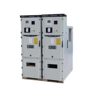
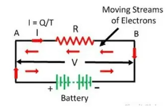
The RMRTBB series reactive power compensation cabinet is designed for 1kV–35kV power frequency systems. It serves as a shunt capacitor bank to compensate for inductive reactive power in the system, thereby improving the power factor, enhancing voltage quality, reducing line losses, and increasing the load capacity of electrical equipment. This ensures a safer, more reliable, and more economical operation of power distribution networks.

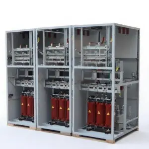
When connected in series with reactors, the cabinet can effectively suppress harmonics, ensuring the safety and reliability of both the device itself and the connected power grid.

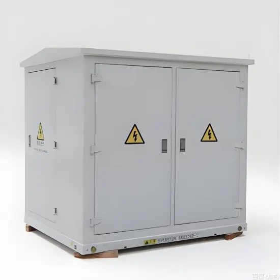
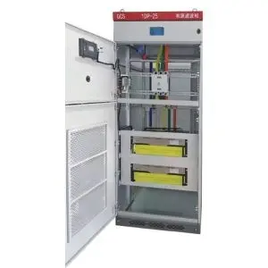
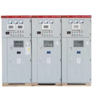
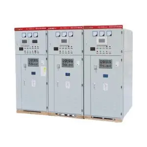
The cabinet adopts a fully enclosed structure with a high protection rating. Each cabinet is equipped with live status and current indication components. It can be installed independently or combined with KYN28/KYN61 switchgear. The system supports both fixed compensation and manual or automatic group switching, based on user requirements.

Product Overview

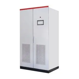
The RMRTBB series reactive power compensation cabinet is designed for power frequency systems with rated voltages from 1kV to 35kV. It functions as a shunt capacitor bank that compensates for inductive reactive power in the system. This improves the power factor, enhances voltage stability, reduces energy losses, and increases the effective capacity of electrical equipment.

By connecting series reactors, the cabinet can suppress harmonics and ensure safe, reliable operation for both the device and the connected grid. It adopts a fully enclosed structure with a high protection level, featuring live status and current indicators. Each cabinet can operate independently or be combined with KYN28/KYN61 switchgear. The compensation method can be fixed or configured for manual or automatic group switching according to user needs.

Performance Features

  • Uses high-quality three-phase capacitor elements with excellent sealing and low loss characteristics, ensuring stable operation and high discharge voltage.
  • The discharge circuit design ensures that the residual voltage drops below 50V within three minutes after disconnection.
  • Effectively improves the system power factor up to 0.95 or higher, reducing line current by 10–20%.
  • Enhances equipment efficiency, improves voltage stability, and reduces power loss in the distribution network.
  • Equipped with live status indicators, electromagnetic locks, and viewing windows for safe and convenient operation.
  • Compact cabinet design allows seamless integration with switchgear, providing reliable and synchronized performance.

Main Technical Parameters

Parameter Specification
Rated Voltage 10(6)–35kV
Rated Frequency 50Hz
Rated Capacity 50–20,000kvar
Neutral Connection Isolated neutral or non-effective grounding

Operating Conditions

  • Installation Environment: Indoor or outdoor
  • Ambient Temperature: −40°C to +45°C
  • Relative Humidity: ≤90% (at 25°C)
  • Altitude: ≤4500m
  • Site Conditions: Free from severe vibration, corrosive gases, steam, or explosive dust.

Working Principle and Features

  • The cabinet mainly includes high-voltage parallel capacitors, reactors, circuit breakers (vacuum type), current transformers, discharge resistors, and control/protection units.
  • It supports automatic or manual group control, allowing the system to adjust reactive compensation levels according to real-time load demand for optimal energy efficiency.
  • Each capacitor group is equipped with discharge resistors that ensure the residual voltage drops below 50V within five minutes after disconnection.
  • Series reactors are used to limit inrush current and suppress harmonics — typically 4.5–6% for 6kV systems and 12–13% for 10kV systems.
  • The cabinet body is designed for excellent thermal and dynamic stability, with observation windows, electromagnetic locks, and reinforced grounding for safety.
  • Adopts anti-condensation design with top-mounted ventilation and pressure-relief mechanisms to prevent internal overpressure.
  • Modular dimensions and customizable layouts are available upon request.
  • The control system provides automatic group switching, monitoring, protection, and communication functions.
  • Equipped with comprehensive protection, including overcurrent, overvoltage, unbalanced load, and short-circuit protection.
  • Designed for long-term operation at 1.0× rated voltage, and can withstand up to 1.3× rated voltage for short durations.
Know your supplier
Online store
On-time delivery rate
Response time
100.0%
≤4h
Company overview
Workplace: 30000m² Total staff: Highest Annual Export(usD): 100000000
Workplace: 30000m²
Total staff:
Highest Annual Export(usD): 100000000
Services
Business Type: Design/Manufacture/Sales
Main Categories: High Voltage Electrical Apparatus/Low Voltage Electrical Apparatus/Instrument meters/New energy/Tester/Robot
Whole life care manager
Whole-life care management services for equipment procurement, use, maintenance, and after-sales, ensuring safe operation of electrical equipment, continuous control, and worry-free electricity consumption.
The equipment supplier has passed platform qualification certification and technical evaluation, ensuring compliance, professionalism, and reliability from the source.

Related Products

Related Knowledges

  • What is Electrical Energy Definition Formula Unit of Electrical Energy
    What is Electrical Energy?Before explaining what electrical energy is, let us try to review the potential difference between two points in an electric field.Suppose potential difference between point A and point B in an electric is v volts.As per the definition of potential difference we can say, if one positive unit electrical charge that is a body containing one-coulomb positive charge travels from point A to point B, it will do v joules work.Now instead of one-coulomb charge if q coulomb char
    03/09/2024
Haven't found the right supplier yet? Let matching verified suppliers find you. Get Quotation Now
Haven't found the right supplier yet? Let matching verified suppliers find you.
Get Quotation Now
Send inquiry
+86
Click to upload file
Download
Get the IEE Business Application
Use the IEE-Business app to find equipment, obtain solutions, connect with experts, and participate in industry collaboration anytime, anywhere—fully supporting the development of your power projects and business.