
| Brand | Transformer Parts |
| Model NO. | WSLD Series electric cage tap changer |
| Rated voltage | 35kV |
| Rated normal current | 800A |
| Methods of regulation | Neutral voltage regulation |
| number of taps | 5~10 |
| number of position | 5~10 |
| Series | WSLD Series |
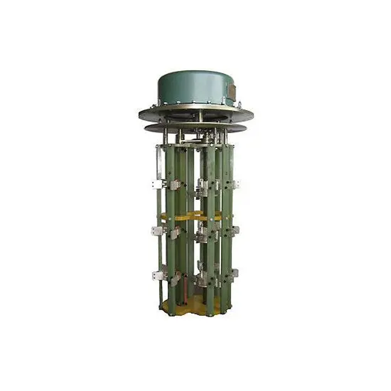
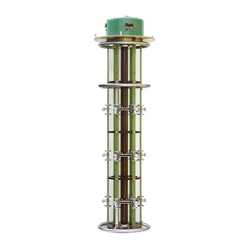
Overview
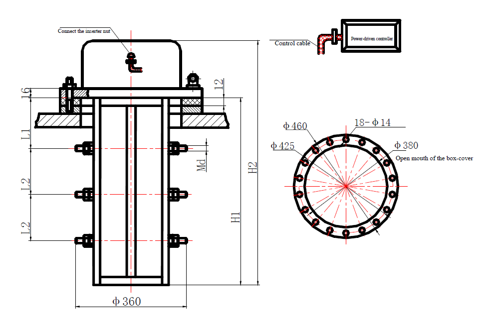
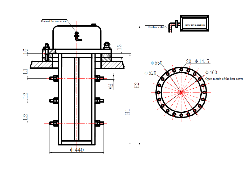
WSLD Series Non-excitative tap-changer belongs to a cage-like structure without oil container, which can be directly installed in the oil tank of the transformer. According the different outline structures, the switch can be divided into vertical, bell and horizontal types.
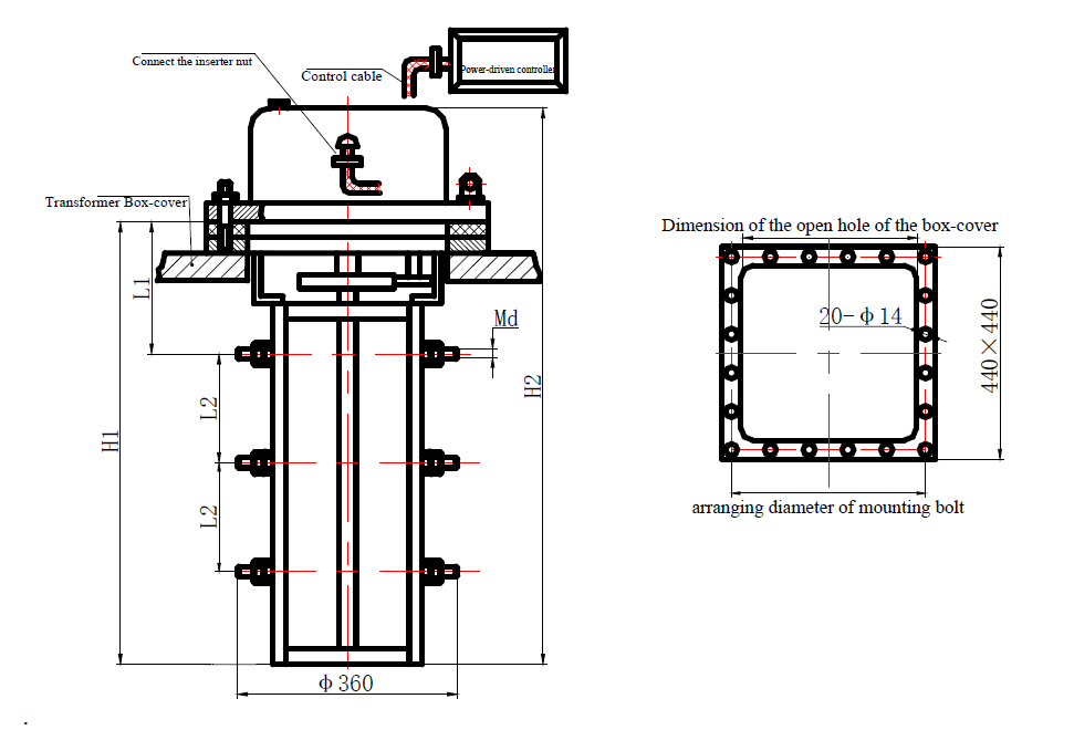
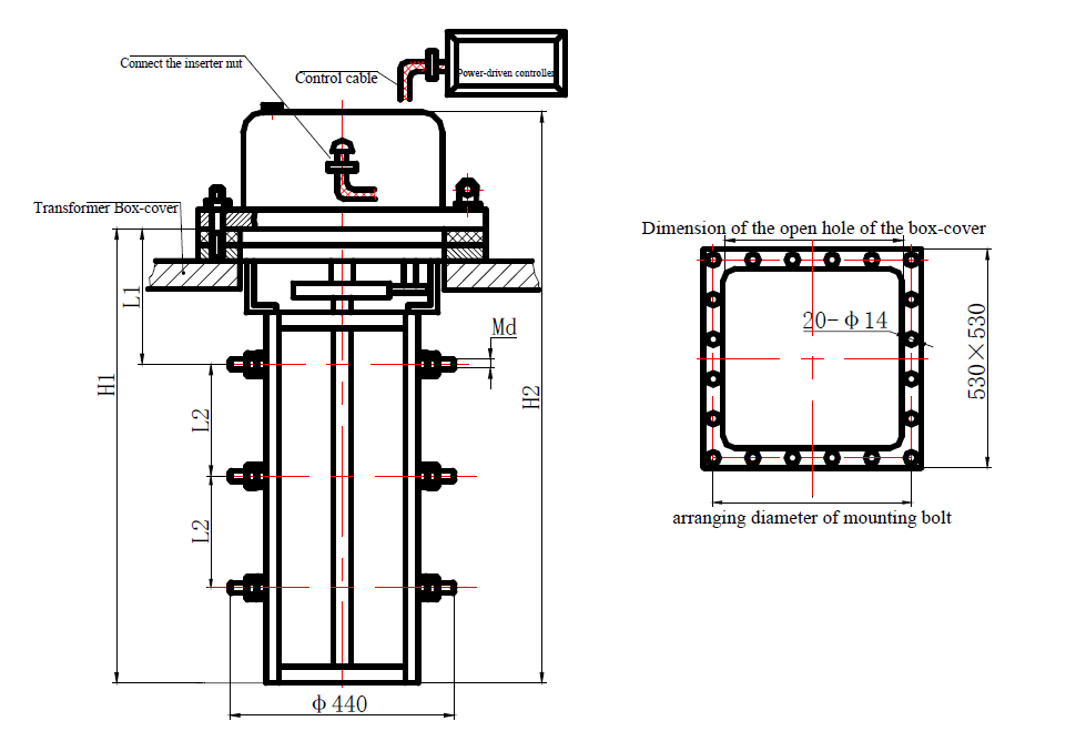
outline
Switch type |
Rated Voltage kV |
Position of Voltage regulation |
Installation Dimension |
|||
L1 |
L2 |
H1 |
H2 |
|||
WSLⅡDL200 - 400/10 - 6X5 - 10X9 F |
10 |
Central part |
210 |
110 |
540 |
720 |
WSLⅢDL200 - 400/10 - 5X5 - 10X10 F |
10 |
Neutral Point |
210 |
110 |
540 |
720 |
WSLⅡDL630 - 800/10 - 6X5 - 10X;9 F |
10 |
Central part |
230 |
130 |
610 |
790 |
WSLⅢDL630 - 800/10 - 5X5 - 10X0 F |
10 |
Neutral Point |
230 |
130 |
610 |
790 |
WSLⅡDL200 - 400/35 - 6X5 - 10X9 F |
35 |
Central part |
275 |
170 |
710 |
890 |
WSLⅢDL200 - 400/35 - 5X5 - 10X10 F |
35 |
Neutral Point |
275 |
170 |
710 |
890 |
WSLⅡDL630 - 800/35 - 6X5 - 10X9 F |
35 |
Central part |
300 |
195 |
810 |
990 |
WSLⅢDL630 - 800/35 - 5X5 - 10&X10 F |
35 |
Neutral Point |
310 |
200 |
815 |
990 |
Switch type |
Rated Voltage kV |
Position of Voltage regulation |
Installation Dimension |
|||
L1 |
L2 |
H1 |
H2 |
|||
| WSLⅡDL200~400/10 - 11X10~14X13 F | 10 |
Central part |
210 |
110 |
540 |
720 |
| WSLⅢDL200~400/10 - 11X11~14X14 F | 10 |
Neutral Point |
210 |
110 |
540 |
720 |
| WSLⅡDL630~800/10 - 11X10~12X11 F | 10 |
Central part |
230 |
130 |
610 |
790 |
| WSLⅢDL630~800/10 - 11X11~12X12 F | 10 |
Neutral Point |
230 |
130 |
610 |
790 |
| WSLⅡDL200~400/35 - 11X10~14X13 F | 35 |
Central part |
275 |
170 |
710 |
890 |
| WSLⅢDL200~400/35 - 11X11~14X14 F | 35 |
Neutral Point |
275 |
170 |
710 |
890 |
| WSLⅡDL630~800/35 - 11X10~12X11 F | 35 |
Central part |
300 |
195 |
810 |
990 |
| WSLⅢDL630~800/35 - 11X11~12X12 F | 35 |
Neutral Point |
310 |
200 |
815 |
990 |
Switch type |
Rated Voltage kV |
Position of Voltage-regulation |
Installation Dimension |
|||
L1 |
L2 |
H1 |
H2 |
|||
WSⅡJLDL200~630/10 - 4×3~10×9 Y |
10 |
Central part |
150 |
110 |
480 |
716 |
WSⅡJLDL200~630/10 - 5×5~10×10 Y |
10 |
Neutral Point |
150 |
110 |
480 |
716 |
WSⅡJLDL800/10 - 6×5~10×9 Y |
10 |
Central part |
170 |
130 |
550 |
786 |
WSⅡJLDL800/10 - 5×5~10×10 Y |
10 |
Neutral Point |
170 |
130 |
550 |
786 |
WSⅡJLDL200~630/35 - 6×5~10×9 Y |
35 |
Central part |
210 |
170 |
650 |
886 |
WSⅡJLDL200~630/35 - 5×5~10×10 Y |
35 |
Neutral Point |
210 |
170 |
650 |
886 |
WSⅡJLDL800/35 - 6×5~10×9 Y |
35 |
Central part |
240 |
195 |
750 |
986 |
WSⅡJLDL800/35 - 5×5~10×10 Y |
35 |
Neutral Point |
240 |
195 |
750 |
986 |
Switch type |
Rated Voltage kV |
Position of Voltage-regulation |
Installation Dimension |
|||
L1 |
L2 |
H1 |
H2 |
|||
WSLⅡDL200~400/10 - 11×10~14×13 F |
10 |
Central part |
210 |
110 |
540 |
720 |
WSLⅢDL200~400/10 - 11×11~14×14 F |
10 |
Neutral Point |
210 |
110 |
540 |
720 |
WSLⅡDL630~800/10 - 11×10~12×11 F |
10 |
Central part |
230 |
130 |
610 |
790 |
WSLⅢDL630~800/10 - 11×11~12×12 F |
10 |
Neutral Point |
230 |
130 |
610 |
790 |
WSLⅡDL200~400/35 - 11×10~14×13 F |
35 |
Central part |
275 |
170 |
710 |
890 |
WSLⅢDL200~400/35 - 11×11~14×14 F |
35 |
Neutral Point |
275 |
170 |
710 |
890 |
WSLⅡDL630~800/35 - 11×10~12×11 F |
35 |
Central part |
300 |
195 |
810 |
990 |
WSLⅢDL630~800/35 - 11×11~12×12 F |
35 |
Neutral Point |
310 |
200 |
815 |
990 |
Switch type |
Rated Voltage kV |
Position of Voltage-regulation |
Installation Dimension |
|||
L1 |
L2 |
H1 |
H2 |
|||
WSL I DL 125~630/10 - 5×5~8×8 Y |
10 |
Terminal port |
150 |
110 |
480 |
716 |
WSL I DL 125~630/10 - 9×9~11×11 Y |
10 |
Terminal port |
150 |
150 |
600 |
836 |
WSL I DL 125~630/35 - 5×5~8×8 Y |
35 |
Terminal port |
210 |
170 |
650 |
886 |
WSL I DL 125~630/35 - 9×9 Y |
35 |
Terminal port |
210 |
210 |
780 |
1016 |
Switch type |
Rated Voltage kV |
Position of Voltage-regulation |
Installation Dimension |
|||
L1 |
L2 |
H1 |
H2 |
|||
WSL I DL 200~630/10 - 10×10~13×13 Y |
10 |
Terminal port |
150 |
150 |
600 |
836 |
WSL I DL 630/10 - 10×10~13×13 Y |
10 |
Terminal port |
150 |
150 |
600 |
836 |
WSL I DL 200~400/35 - 10×10~13×13 Y |
35 |
Terminal port |
210 |
210 |
780 |
1016 |
WSL I DL 630/35 - 10×10~11×11 Y |
35 |
Terminal port |
210 |
210 |
780 |
1016 |
Switch type |
Rated Voltage kV |
Position of Voltage-regulation |
Installation Dimension |
|||
L1 |
L2 |
H1 |
H2 |
|||
WSLNDL200~630/10 - 2×2 Y |
10 |
Y / △ |
150 |
110 |
480 |
716 |
WSLNDL800/10 - 2×2 Y |
10 |
Y / △ |
170 |
130 |
550 |
786 |
WSLNDL200~630/35 - 2×2 Y |
35 |
Y / △ |
210 |
170 |
650 |
886 |
WSLNDL800/35 - 2×2 Y |
35 |
Y / △ |
240 |
195 |
750 |
986 |
Switch type |
Rated Voltage kV |
Position of Voltage-regulation |
Installation Dimension |
|||
L1 |
L2 |
H1 |
H2 |
|||
WSL V DL200~630/10 - 4×2 Y |
10 |
Series-Parallel |
150 |
110 |
480 |
716 |
WSL V DL800/10 - 4×2 Y |
10 |
Series-Parallel |
170 |
130 |
550 |
786 |
WSL V DL200~630/35 - 4×2 Y |
35 |
Series-Parallel |
210 |
170 |
650 |
886 |
WSL V DL800/35 - 4×2 Y |
35 |
Series-Parallel |
240 |
195 |
750 |
98 |
application
This series consists of an electric transmission mechanism, a switch body, and an electric controller. It is designed for use in oil-immersed transformers with a maximum equipment voltage of 40.5 kV or lower and a rated current of 630A or lower. The tap and switch functions can be operated electrically or manually when the transformer is de-energized.
If you need to know about more product; welcome contact us.→→→