A Direct Replacement Solution for Legacy AIS Modernization

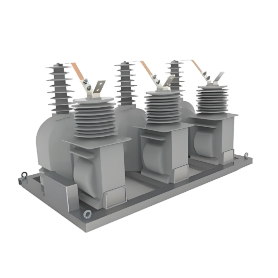
Executive Summary: Facing aging conventional Current Transformers (CTs) and Voltage Transformers (VTs) in Air-Insulated Substations (AIS)? Modernization can't mean rebuilding the substation. The CIT (Combined Instrument Transformer) is engineered specifically as a robust, drop-in replacement for your legacy units. Preserving existing foundations and busbar connections, it delivers essential analog compatibility today while seamlessly enabling your phased digital future. Prioritizing ruggedness and field-proven reliability, it builds trust for replacing established technologies.
The Challenge: Modernizing Mature AIS Infrastructure
AIS assets form the backbone of global transmission and distribution networks. Thousands of sites rely on decades-old CTs and VTs nearing end-of-life. Replacing them presents unique challenges:
- High Cost of Structural Change: Demolishing foundations, altering busbars, or expanding structures is prohibitively expensive and disruptive.
- Relay Compatibility Dependency: Critical protection and metering schemes rely on established 5A/1A and 110V/100V analog inputs.
- Migration Strategy: Immediate wholesale replacement with digital-only solutions is often impractical; a phased approach is essential.
- Trust Hurdle: Legacy CTs/VTs have a proven track record. New technologies must demonstrate comparable reliability under harsh field conditions to gain acceptance.
Direct Replacement, Dual Outputs, Proven Reliability
This CIT is the answer, designed from the ground up as a direct, retrofittable upgrade for conventional CTs and VTs in AIS environments:
- Direct "Drop-In" Retrofit Design (Core Enabler):
- Precision Footprint Matching: Dimensions and mass are engineered to perfectly replicate the original CT/VT units being replaced.
- Identical Mounting & Busbar Interfaces: Utilizes the existing foundation bolts and matches the existing busbar tap dimensions/configurations (e.g., clamp type, bolt holes). No cutting, welding, or busbar modifications required.
- Standard Terminal Box Placement: Secondary connections terminate in locations familiar to technicians, positioned like the originals.
- Significant Installation Advantages:
- Radically Reduced Downtime: Installation windows shrink from days to hours.
- Eliminated Civil Costs: Avoids concrete work, structural modifications.
- Minimized Risk: Simplified engineering, less complex lift plan, reduced potential for errors during busbar work.
- Hybrid Output System: Supporting Today & Tomorrow:
- Legacy Analog Interface:
- Current Outputs: Standard burden-compatible outputs: 1A (5VA typical) and 5A (15VA or 30VA typical) per protection/metering core.
- Voltage Outputs: Standard ratio-compatible outputs: 100V (Line-Neutral) and 110V (Line-Neutral), suitable for relays and meters. 110V (Line-Line) option available where required.
- Modern Digital Interface:
- Standards-Based: Digital output compliant with IEC 61850-9-2LE Sampled Values (SV) over Ethernet.
- Advanced Capabilities: Provides merged, synchronized, high-resolution sampled current and voltage data, enabling new possibilities for protection, control, and condition monitoring within digital substation architectures.
- Phased Migration Pathway: Utilities can:
- Phase 1: Connect existing analog protection/control systems to the CIT. Critical functions remain unchanged.
- Phase 2: Route the digital SV stream to new Intelligent Electronic Devices (IEDs) or gateways for advanced applications or new bays.
- Phase 3: Gradually decommission legacy IEDs as digital systems prove reliable, minimizing risk and spreading investment.
- Ruggedized Design for Proven Field Reliability (Building Trust):
- Extreme Environment Ready: Components selected and sealed to withstand temperature extremes (-40°C to +70°C operational), high humidity (IP67 ingress protection standard), salt fog (C5-M corrosion resistance), and severe pollution levels.
- Seismic Performance: Designed to meet IEC 61869/IEEE C37 seismic requirements suitable for the installation zone.
- Advanced Insulation System: Utilizes solid core insulation (e.g., SF6-free dry design with silicone shed composite housing, or SF6 gas) optimized for stability and long life under switching surges and temporary overvoltages (TOVs).
- Thermal & Overload Stability: Generously rated primary conductors and secondary windings ensure performance under fault conditions and overload scenarios. Proven thermal stability test compliance.
- Reliability by Design: Employs robust sensor technology (e.g., optimized Low-Power Coreless CTs/LPCTs, resistive/capacitive voltage dividers) with minimal active electronics. Focus on simplicity in critical paths.
- Validation Focus: Extensive type testing (IEC 61869, IEEE C57.13) plus rigorous pre-deployment pilot testing in actual grid environments under varied operating conditions to build utility confidence and demonstrate operational equivalence to legacy technologies.
- Technical Specifications Overview:
|
Feature |
Specification |
|
Primary Voltage |
Matched to existing application (e.g., 72.5kV - 550kV) |
|
Primary Current |
Matched to existing busbar rating |
|
Analog Outputs |
1A/5A CT Cores, 100V/110V VT Outputs (Std ratios) |
|
Digital Output |
IEC 61850-9-2LE SV over Fiber/Ethernet |
|
Accuracy (Analog) |
Typically 0.2 / 5P for VT, 5P / 5TPE for CT cores |
|
Accuracy (Digital) |
Typically Class 0.2 (Meas), 5TPE (Prot) |
|
Environmental |
-40°C to +70°C Ambient, IP67, C5-M Corrosion Res. |
|
Seismic |
Zone 3 / Zone 4 per IEEE 693 |
|
Standards |
IEC 61869, IEEE C57.13, Local Utility Standards |
Value Proposition: Reducing Risk & Cost for Grid Operators
- Radically Lower Installation Cost & Time: Eliminates structural modifications and complex busbar work. Commissioning faster.
- De-risked Modernization: Maintains compatibility with existing, trusted protective relaying during transition. Proven analog reliability.
- Future-Proof Investment: Built-in digital capabilities ensure readiness for digital substations without immediate obsolescence.
- Enhanced Resilience: Rugged design offers longevity comparable to conventional CTs/VTs, minimizing future replacement cycles.
- Reduced Substation Footprint: Replaces two conventional devices with one, improving buswork clarity and freeing space.
- Unified Data Source: Single device provides synchronized current and voltage data, improving measurement correlation and enabling advanced analytics.