Harmonic Mitigation Solution for New Energy Power Stations: Comprehensive Management of High-Frequency Harmonics in Photovoltaic Power Plants

Ⅰ. Problem Scenario
High-frequency harmonic injection from PV plant inverter clusters
During operation of large-scale centralized PV power plants, multiple inverters operating in parallel generate wide-band harmonics in the 150-2500Hz range (primarily the 23rd to 49th harmonics), leading to the following grid-side issues:
- Current Total Harmonic Distortion (THDi) reaching 12.3%, significantly exceeding IEEE 519-2014 standard limits.
- Causing capacitor bank overload, overheating, and protective device maloperation.
- Increased Electromagnetic Interference (EMI) affecting nearby sensitive equipment.
II. Core Solution
Adoption of an LC passive filter topology, constructing efficient harmonic absorption circuits using customized reactors + capacitor banks.
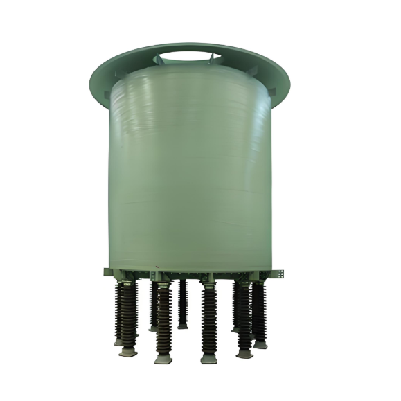
- Key Equipment Selection
|
Equipment Type |
Model/Specification |
Core Function |
|
Dry-Type Iron-Core Series Reactor |
CKSC Type (Custom Design) |
Provides precise inductive reactance, suppressing high-frequency harmonics. |
|
Filter Capacitor Bank |
BSMJ Type (Matched Selection) |
Resonates with reactors to absorb specific harmonic bands. |
- Technical Parameter Design
Reactor Inductance: 0.5mH ±5% (@50Hz fundamental frequency)
Quality Factor (Q): >50 (Ensures low-loss high-frequency filtering)
Insulation Class: Class H (Long-term withstand temperature 180°C)
Reactance Ratio Configuration: 5.5% (Optimized for 23rd-49th high-frequency band)
Topology Structure: Delta (Δ) Connection (Enhances high-order harmonic shunting capability) - Filter System Design Key Points
Resonant Frequency Calculation:
f_res = 1/(2π√(L·C)) = 2110Hz
Accurately covers the target frequency band (150-2500Hz), achieving local absorption of high-frequency harmonics.
III. EMC Mitigation Effectiveness Validation
|
Indicator |
Before Mitigation |
After Mitigation |
Standard Limit |
|
THDi |
12.3% |
3.8% |
≤5% (IEEE 519) |
|
Individual Harmonic Distortion |
Up to 8.2% |
≤1.5% |
Compliant with GB/T 14549 |
|
Capacitor Temperature Rise |
75K |
45K |
Compliant with IEC 60831 |
IV. Engineering Implementation Advantages
- High-Efficiency Filtering:
The 5.5% reactance ratio design specifically suppresses harmonics above the 23rd order, providing a 40% improvement in high-frequency response compared to traditional 7% schemes. - Safety and Reliability:
The Class H temperature rise insulation system ensures stable equipment operation in outdoor environments ranging from -40°C to +65°C. - Cost Optimization:
The low-loss design (Q > 50) results in additional system power consumption of < 0.3% of output power.
V. Deployment Recommendations
- Installation Location: Low-voltage side busbar of the 35kV collection substation.
- Configuration: Each 2Mvar capacitor bank series-connected with 10 CKSC reactors (Group-based automatic switching).
- Monitoring Requirement: Install an online harmonic analyzer to track THDi changes in real-time.
Solution Value: Effectively resolves high-frequency harmonic pollution in new energy power stations, extends capacitor lifespan by over 37%, and avoids PV output curtailment due to harmonic violation penalties.