• Product
  • Suppliers
  • Manufacturers
  • Solutions
  • Free tools
  • Knowledges
  • Experts
  • Communities
Search


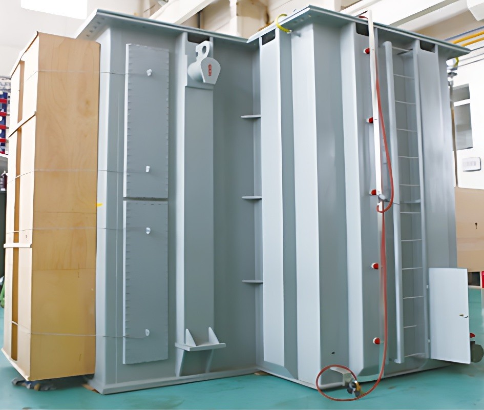
High-Efficiency Thermal Management Solution for Special Transformers Guaranteeing Core Performance & Extending Equipment Lifespan

Rockwill
17yrs 700++ staff 108000m²+m² US$150,000,000+ China

Ⅰ. Core Perspective

Addressing heat accumulation challenges in special transformers under severe operating conditions, this solution proposes systematic thermal dissipation and temperature control optimization strategies:

  • Extreme Loading:​ Continuous overload, impact loads.
  • High Harmonic Pollution:​ Additional losses caused by non-linear loads.
  • High Ambient Temperatures:​ Outdoor/enclosed spaces with sustained ambient temperatures ≥40°C.

II. Key Solution Points

(A) Precision Thermal Simulation & Design Optimization

  1. Thermal Digital Twin Model
    • Utilizes CFD software (FloTHERM/Star-CCM+) to build a 3D thermal-fluid coupling model.
    • Accurately simulates oil flow paths, winding hot-spot distribution, and radiator efficiency.
    • Outputs optimized schemes: Achieves >15% hotspot temperature reduction through heat dissipation structure adjustments.

(B) Customized Cooling System Design

Cooling Method

Technical Solution

Applicable Scenarios

Natural Cooling

► Biomimetic heat sink design (fin density gradient distribution)
► Blackbody radiation treatment on tank surface (ε≥0.95)

Standard load, low ambient temperature

Forced Air Cooling

► Vortex axial fan array (IP55 protection rating)
► Temperature-controlled start/stop strategy (50°C start / 40°C stop)

High-altitude/high-temperature environments, periodic overloads

Forced Oil Circulation

► Magnetic levitation oil pump (energy consumption <30% of conventional pumps)
► Air-cooled: Variable-frequency fans + aluminum corrugated radiators
► Water-cooled: Plate heat exchangers (ΔT≤3K)

Submerged arc furnace transformers, traction rectifier transformers, marine transformers

Heat Pipe Assisted

► Embedded ultra-thermal conductive heat pipes (thermal conductivity >5000 W/m·K)
► Targeting local hotspots (core clamps, HV leads, etc.)

Space-constrained high-density winding regions

(C) Oil Flow Control Optimization

  • Enhanced Oil Guiding Design:

A[Oil Inlet] --> B[Silicon Steel Guide Channels]

B --> C[Axial Winding Oil Ducts]

C --> D[Hotspot Reinforced Spray Nozzles]

D --> E[Top Oil Outlet]

  • Achieves ≥300% increase in oil flow velocity in hotspot regions, resulting in 8-12K temperature reduction.

(D) Intelligent Temperature Control System

Functional Module

Technical Implementation

Monitoring System

► Distributed Optical Fiber Temperature Sensing (±0.5°C accuracy)
► Real-time winding hotspot reconstruction algorithm
► Ambient temperature & humidity compensation monitoring

Control Strategy

► PID stepless speed control for fans/oil pumps (20-100%)
► Load-temperature linkage control (I²T protection model)

Smart IoT

► IEC 61850 communication protocol
► Alarm thresholds: 3-level alarms triggered by hotspots >105°C
► Real-time display of life consumption

III. Target Outcomes & Verification Standards

  1. Temperature Control
    • Winding Hotspot Temperature: ≤95°C (rated load) / ≤115°C (2-hour emergency overload)
    • Top Oil Temperature Rise: ≤45K (compliant with IEC 60076-7)
  2. Lifespan Assurance
    • Based on the 10°C Rule (Montsinger's Rule):L = L₀ × 2^[(98°C - T_hotspot)/6]
    • Ensures insulation thermal aging <20% over the 30-year design lifespan.
  3. Efficiency Improvement
    • Reduced No-Load Losses: 12% reduction (low eddy current design)
    • Cooling System Energy Consumption: <5% of total losses

IV. Typical Application Scenarios

Special Transformer Type

Thermal Management Solution Combination

Arc Furnace Transformers

Forced Oil Circulation + Water Cooling + Heat Pipe Assistance

Traction Rectifier Transformers

Forced Air Cooling + Intelligent Multi-stage Speed Control

Offshore Wind Power Transformers

Sealed Heat Pipe Cooling System + Triple-protection Coating (Anti-corrosion/Anti-fouling/Anti-moisture)

Data Center Cast-Resin Transformers

Fan Group Control + CFD-based Airflow Optimization

07/28/2025
Recommended
Solution for Medium-Voltage Motor Control and Protection Using Vacuum Contactor-Fuse (VCF) in a Coal Conveying System
Project BackgroundA coal conveying system comprises 15 belt conveyors driven by medium-voltage motors. The system operates under complex conditions, with motors often subjected to heavy loads and frequent starts. To address these challenges and achieve effective control and reliable protection during motor startup, the project comprehensively adopts Vacuum Contactor-Fuse (VCF) combination devices for the 6kV medium-voltage motor power distribution. This solution details the technical features,
ABB Vacuum Contactor KC2 Power Supply System Technical Transformation Plan
Issue Overview​The 10kV air compressor starting system of a company utilizes the ABB vacuum contactor KC2 as the control component for the operating circuit. The dedicated wide-voltage power supply module paired with this contactor presents the following issues:​Frequent failures: The power supply module fails to properly transition the voltage from 300V to 12V, resulting in fuse blowouts.​Poor heat dissipation: Enclosed installation of the module leads to insufficient heat dissipation, acceler
Dedicated Vacuum Contactor Solution for Port Shore Power Systems
I. Background and Challenges​Shore power systems have become core technical equipment for ports to reduce carbon emissions and noise pollution. However, these systems face two major challenges in the harsh operational environment of ports:​Severe Environmental Corrosion: High humidity and salt spray in port areas cause serious corrosion to metal components and enclosures of electrical equipment, significantly impacting electrical lifespan and operational reliability.​High Switching Requirements:
Vacuum Contactor Industrial Power Control Solutions
Application Background and Pain Point Analysis​In modern industrial manufacturing power control systems, traditional contactors exhibit significant limitations under specific operating conditions:• ​Frequent Start-Stop Operations: Traditional contactors have limited mechanical lifespan, with frequent operations leading to coil burnout and mechanical jamming.• ​Poor Adaptability to Harsh Environments: Contacts are prone to oxidation in dusty environments, resulting in increased contact
Seed Inquiry
Download
Get the IEE Business Application
Use the IEE-Business app to find equipment, obtain solutions, connect with experts, and participate in industry collaboration anytime, anywhere—fully supporting the development of your power projects and business.