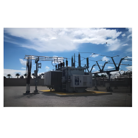
1. Background and Challenges
With the continuous growth of power loads and increasingly stringent requirements for stable grid operation, transmission transformers face severe challenges regarding operational efficiency, temperature rise control, and long-term reliability. Excessive operating temperatures accelerate the aging of insulation materials, shorten equipment lifespan, and increase failure risks. High magnetic circuit losses (primarily iron loss and copper loss) reduce energy utilization efficiency, leading to unnecessary operational costs. To address the two core issues commonly found in transmission transformers—excessive temperature rise and significant magnetic circuit losses—this comprehensive solution is formulated.
2. Solution Objectives
- Significantly Reduce Operating Temperatures: Control the transformer's top-oil temperature and winding hotspot temperature within safe operating margins.
- Effectively Reduce Magnetic Circuit Losses: Focus on reducing no-load losses (iron loss) and load losses (copper loss), enhancing overall operational efficiency.
- Enhance Operational Reliability: Reduce failure rates caused by overheating and excessive losses, extending transformer service life.
- Optimize Total Life Cycle Cost: Improve the transformer's economic efficiency through energy savings and reduced maintenance frequency.
3. Core Mitigation Measures
This solution adopts an integrated strategy of "Source Control of Losses + Enhanced Heat Dissipation Capability + Precise Condition Management":
3.1 Cooling System Optimization and Upgrade, Improving Heat Dissipation Efficiency (Addressing Temperature Rise)
- Employ High-Efficiency Cooling Methods:
- Forced Air Cooling (OFAF/ODAF): Retrofit existing naturally air-cooled (ONAN) or air-forced cooled (ONAF) transformers, or equip new units with high-performance axial fans. Select efficient, low-noise, and weather-resistant fans combined with intelligent airflow control (e.g., automatic start/stop based on temperature or variable frequency drive adjustment) to significantly enhance air convection efficiency on radiator surfaces and rapidly remove heat.
- Forced Oil Water Cooling (OFWF): Prioritized for ultra-high-capacity transformers, units with high load factors, or those operating in high ambient temperatures. Equipped with high-efficiency oil pumps and plate heat exchangers to leverage water's high specific heat capacity for efficient heat exchange. Requires supporting water treatment systems (to prevent scaling and corrosion) and reliability assurance mechanisms (e.g., dual water circuits, standby pumps).
- Heat Pipe Assisted Cooling: Install heat pipe modules at critical points on radiators to efficiently conduct and dissipate local hot spot heat via the phase-change principle.
- Optimize Radiator Structure and Layout:
- Utilize radiators with increased surface area (e.g., finned, panel radiators) and optimized flow path designs.
- Ensure smooth flow paths for cooling media (air or water), eliminate local flow restrictions, and improve heat dissipation uniformity.
- (For air cooling) Optimize fan positioning and duct design to ensure uniform airflow coverage over radiator surfaces, minimizing dead zones.
- Intelligent Cooling Control:
- Automatically adjust cooling system output (fan speed/number, oil pump flow rate) based on real-time monitoring of oil temperature, winding temperature, and ambient temperature. Achieves on-demand cooling, guaranteeing heat dissipation effectiveness while minimizing auxiliary equipment energy consumption.
3.2 Core Material and Structural Optimization, Reducing Iron Loss (Core Magnetic Loss Control)
- Select High-Performance Core Materials:
- Prioritize high-permeability, low-unit-loss cold-rolled silicon steel sheets (e.g., HiB steel) or more advanced amorphous alloy materials (offering significant advantages for no-load loss reduction).
- Strictly control silicon steel sheet thickness, flatness, and insulation coating quality to minimize hysteresis losses and eddy current losses.
- Optimize Core Design and Manufacturing Processes:
- Implement step-lap stacking techniques to minimize magnetic reluctance at joints, reducing additional iron losses.
- Precisely control core stacking factor and clamping force to ensure uniform magnetic path distribution and avoid local over-saturation.
- (Applying Advanced Technologies) Explore techniques like laser scribing (Laser Scribbling) to further optimize material magnetic domain structure.
- Optimize core grounding methods and shielding to reduce stray losses in structural components.
3.3 Winding Design Optimization and Process Improvement, Reducing Copper Loss (Key Magnetic Loss Control)
- Optimize Winding Structure and Electromagnetic Design:
- Precisely calculate ampere-turn distribution, optimize conductor cross-section shape (e.g., using continuously transposed cables - CTC or self-bonding transposed cables - TTC) to minimize circulating current and eddy current losses.
- Reasonably select conductor material (high-conductivity oxygen-free copper) and current density, effectively reducing DC resistance losses while meeting temperature rise constraints.
- Optimize winding height, diameter, and radial dimensions to control leakage flux and reduce stray losses.
- Advanced Manufacturing Processes:
- Ensure uniform winding compactness using constant-tension winding equipment.
- Employ advanced Vacuum Pressure Impregnation (VPI) or resin casting processes to ensure thorough filling of gaps with insulating materials, improving thermal conductivity and mechanical strength, thereby aiding heat dissipation and reducing partial discharges.
3.4 Magnetic Circuit Condition Monitoring and Proactive Maintenance (Closed-loop Management, Ensuring Long-term Performance)
- Implement Precise Magnetic Circuit Condition Monitoring:
- Comprehensively assess magnetic circuit health by integrating online monitoring (e.g., Dissolved Gas Analysis - DGA, high-frequency partial discharge monitoring, vibration/acoustic noise monitoring, infrared thermography) and offline testing (periodic winding deformation testing, no-load & load loss testing, core ground current testing).
- Focus Monitoring: Signs of core multi-point grounding faults, abnormal loss fluctuations, overheating of magnetic shields and clamping structures.
- Establish a Preventive Maintenance Mechanism:
- Develop targeted magnetic circuit maintenance plans based on condition monitoring data and operational history.
- Periodically inspect core and clamping structure grounding: Ensure reliable single-point grounding, promptly detect and rectify multi-point grounding faults (which significantly increase iron losses and cause overheating).
- Inspect magnetic shields, clamps, and other structural components: Check for looseness, overheating, or discharge traces; promptly eliminate abnormalities.
- During core/lid lifting inspections, conduct focused checks and maintenance on core lamination joints and clamping condition.
- Perform in-depth diagnostic analysis on detected upward trends in abnormal losses to identify root causes and implement corrective actions.
4. Expected Benefits
- Significant Reduction in Temperature Rise: Operating temperatures (especially hotspot temperatures) are expected to be effectively controlled, with reductions reaching projected targets (e.g., 15-25%), greatly alleviating thermal aging stress on insulation.
- Effective Reduction in Magnetic Circuit Losses:
- Iron loss (No-Load Loss): Expected reduction of 20-40% through new materials and processes (especially significant when using amorphous alloys).
- Copper loss (Load Loss): Expected reduction of 10-25% through optimized winding design.
- Overall efficiency improvement of 1-3 percentage points, delivering considerable economic benefits and carbon emission reduction.
- Substantial Improvement in Reliability: Failure risks caused by overheating and magnetic circuit abnormalities are significantly reduced, enhancing equipment availability and extending service life.
- Optimized Total Life Cycle Cost: Despite potentially higher upfront investment (e.g., high-performance materials, advanced cooling systems), the benefits derived from long-term energy savings, reduced maintenance costs, and extended lifespan are more substantial, achieving a favorable Return on Investment (ROI).
5. Applicable Scope
This solution applies to newly built and in-service oil-immersed transmission (power) transformers at 35kV voltage level and above. Specific measures can be customized and implemented based on the transformer's capacity, voltage level, operating environment, criticality, and current condition.


