10kV SF₆ Ring Main Units (RMUs) Common Fault Prevention Measures

10kV SF₆ Ring Main Units (RMUs) Common Fault Prevention Measures
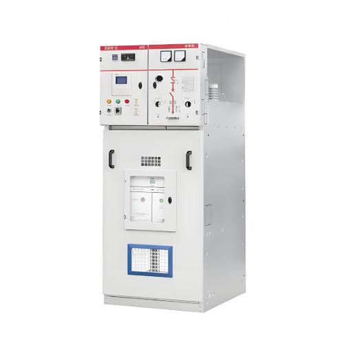
During the development of urban distribution network cabling, 10kV SF₆ Ring Main Units (RMUs) (European-style), serving as ring power supply nodes, have been widely adopted due to their features such as full insulation, complete enclosure, maintenance-free operation, compact size, and flexible, convenient installation. However, as the number of RMUs in use increases, the occurrence of faults within RMUs has also gradually risen.
1 Common Faults
- RMU Busbar Connection Faults: RMU expansion busbars mostly utilize plug-in silicone rubber connectors, fully insulated and shielded to ensure electrical conductivity reliability and resistance to surrounding environmental influences. They allow for arbitrary connection and combination based on actual needs. However, leakage of SF₆ gas, caused by various reasons, reduces the RMU's insulation level and arc-extinguishing capability, making busbar connection faults and insulation breakdowns still likely to occur.
- Faults at the Junction between RMU and Three-Core Cable: During the installation of three-core cables, phase sequence verification is often necessary, requiring the application of external torsional force before fixing. After installation, the internal stress generated by this twisting gradually releases, creating a restoring torque acting on the bushings. This easily leads to bushing cracks, causing high-voltage short circuits.
- Faults at the RMU Cable Termination: The cable compartment space in RMUs is relatively small, placing high demands on the cable termination manufacturing process. Inadequate handling of the conductor, semiconductor layer, or shielding layer can easily lead to cable breakdown due to insufficient creepage distance at the termination.
2 Prevention Measures
- Securing Large Cross-Sectional Cables Entering the RMU:
Three-core cables entering the RMU must be secured using cable clamps directly below the high-voltage bushings. Otherwise, the cable will exert twisting or pulling forces on the bushings. Sustained stress can damage the seal between the bushings and the cabinet, leading to SF₆ gas leakage, bushing cracks, and ultimately high-voltage short circuits.
Ensure the vertical symmetry of the cable cores without twisting. The branch glove should be installed as low as possible, and the cable clamp position should also be as low as possible, with a minimum vertical distance of 750mm from the bushing.
During construction, when feeding the cable from under the RMU foundation into the cable compartment, cut off the end of the cable damaged during pulling. Then, verify the phase sequence, correct the entry angle of the cable into the RMU to align the three cores with their respective bushings. If the cable entry angle is excessive, withdraw the cable back into the cable trench, adjust the angle, re-feed it into the RMU, and secure it with a cable clamp. - Cable Phase Separation and Termination:
When performing phase separation, first secure the lower end of the cable branch glove with a cable clamp, and then trim the cable core lengths.
Align the L2 core with the L2 bushing. Slightly bend the L1 and L3 cores outward from the root first, then align them vertically upwards with their bushings. Screw on the double-ended fixing bolt, temporarily hang the cable lug on the bushing, compare the cable length, and saw off any excess core. Ensure the three cable cores are of correct, equal length and flush to avoid stress on the bushings and poor contact between the cable lug and the bushing face.
Failing to secure the cable before trimming the core lengths means there is no reference point, leading to errors. Therefore, securing the cable first is crucial.
Pay attention to the following points during cable stripping: - Stripping dimensions must strictly follow the specifications provided by the cable T-body connector manufacturer and their accompanying process dimensions.
- Extreme care must be taken when removing outer layers to avoid damaging inner layers.
- Absolutely avoid longitudinal scratches on the core insulation to prevent internal creepage.
- Always use the manufacturer's designated special cleaning wipes; avoid using alternatives like industrial alcohol.
- For installation lubricant, it is recommended to use polyfluoropolyether (PFPE) grease products. These are non-reactive with silicone rubber, ensuring long-term sealing and insulation performance. Avoid using silicone-based greases, as mutual dissolution and drying with silicone rubber can create a risk of interfacial creepage.
- Ensuring Proper Fit Between Stress Cone and Cable Cross-Section:
The interference fit (overlap) must be appropriate. Excessive interference makes installation difficult and risks cracking the components. Insufficient interference compromises sealing and can lead to severe surface discharge.
For cable T-body connectors, the stress cone, insulating outer sheath, and the cable itself have specific relative positioning requirements, offering less flexibility. Installation must be performed strictly according to the requirements (standards vary between manufacturers) to meet stress control and insulation sealing demands.
Furthermore, during installation, ensure the stress cone body is positioned within the vertical section of the cable where possible, to guarantee the best sealing effect. Take special care to prevent sharp objects from scratching the inner or outer surfaces of silicone rubber stress cone components. Apply the designated installation lubricant evenly and separately to the contact surfaces forming the interference fit. - Installing Elbow Connectors:
The conductor connection within cable elbow connectors is completed inside the insulated outer housing, making the contact condition difficult to observe and inconvenient to test. Therefore, it must be ensured that the lug face is parallel and in flush contact with the conductive face of the RMU bushing. This minimizes the stress exerted by the lug on the bushing while ensuring full, good contact to prevent heating during operation.
The crimping of cable lugs onto wire cores must follow the installation procedure. Pay strict attention to the orientation of the lug face; it should be parallel to the copper face of the busbar bushing to ensure flush contact. When using a crimping tool, hold the dies closed for 10-15 seconds after reaching the full crimp position to allow the metal at the crimp to stabilize plastically. After crimping, use a file to smooth any burrs or sharp edges on the lug surface, then clean both the core insulation and the lug. Slide the cable lug onto the fixing stud, push the cable elbow connector into the bushing, and install it ensuring the lug face is in tight, flush contact with the copper face of the bushing.
08/13/2025
Recommended

Integrated Wind-Solar Hybrid Power Solution for Remote Islands
AbstractThis proposal presents an innovative integrated energy solution that deeply combines wind power, photovoltaic power generation, pumped hydro storage, and seawater desalination technologies. It aims to systematically address the core challenges faced by remote islands, including difficult grid coverage, high costs of diesel power generation, limitations of traditional battery storage, and scarcity of freshwater resources. The solution achieves synergy and self-sufficiency in "power suppl

An Intelligent Wind-Solar Hybrid System with Fuzzy-PID Control for Enhanced Battery Management and MPPT
AbstractThis proposal presents a wind-solar hybrid power generation system based on advanced control technology, aiming to efficiently and economically address the power needs of remote areas and special application scenarios. The core of the system lies in an intelligent control system centered around an ATmega16 microprocessor. This system performs Maximum Power Point Tracking (MPPT) for both wind and solar energy and employs an optimized algorithm combining PID and fuzzy control for precise

Cost-Effective Wind-Solar Hybrid Solution: Buck-Boost Converter & Smart Charging Reduce System Cost
AbstractThis solution proposes an innovative high-efficiency wind-solar hybrid power generation system. Addressing core shortcomings in existing technologies—such as low energy utilization, short battery lifespan, and poor system stability—the system employs fully digitally controlled buck-boost DC/DC converters, interleaved parallel technology, and an intelligent three-stage charging algorithm. This enables Maximum Power Point Tracking (MPPT) over a wider range of wind speeds and s
Hybrid Wind-Solar Power System Optimization: A Comprehensive Design Solution for Off-Grid Applications
Introduction and Background1.1 Challenges of Single-Source Power Generation SystemsTraditional standalone photovoltaic (PV) or wind power generation systems have inherent drawbacks. PV power generation is affected by diurnal cycles and weather conditions, while wind power generation relies on unstable wind resources, leading to significant fluctuations in power output. To ensure a continuous power supply, large-capacity battery banks are necessary for energy storage and balance. However, bat


